CHIMNEYS AND VENTS
-
SECTION 501 (IFGC)
GENERAL501.1 Scope.
This chapter shall govern the installation, maintenance, repair and approval of factory-built chimneys, chimney liners, vents and connectors and the utilization of masonry chimneys serving gas-fired appliances. The requirements for the installation, maintenance, repair and approval of factory-built chimneys, chimney liners, vents and connectors serving appliances burning fuels other than fuel gas shall be regulated by the International Mechanical Code. The construction, repair, maintenance and approval of masonry chimneys shall be regulated by the International Building Code.501.2 General.
Every appliance shall discharge the products of combustion to the outdoors, except for appliances exempted by Section 501.8.501.3 Masonry chimneys.
Masonry chimneys shall be constructed in accordance with Section 503.5.3 and the International Building Code.501.4 Minimum size of chimney or vent.
Chimneys and vents shall be sized in accordance with Sections 503 and 504.501.5 Abandoned inlet openings.
Abandoned inlet openings in chimneys and vents shall be closed by an approved method.501.6 Positive pressure.
Where an appliance equipped with a mechanical forced draft system creates a positive pressure in the venting system, the venting system shall be designed for positive pressure applications.501.7 Connection to fireplace.
Connection of any appliance to chimney flues serving fireplaces is prohibited. Refer to IFGC Section 602 for Decorative Appliances for installation in Fireplaces and IFGC Section 603 for Log Lighters.501.7.1 Closure and access.
(Deleted).Deleted
501.7.2 Connection to factory-built fireplace flue.
(Deleted).Deleted
501.7.3 Connection to masonry fireplace flue.
(Deleted).Deleted
501.8 Appliances not required to be vented.
The following appliances shall not be required to be vented.1. Ranges.
2. Built-in domestic cooking units listed and marked for optional venting.
3. Hot plates and laundry stoves.
4. Type 1 clothes dryers (Type 1 clothes dryers shall be exhausted in accordance with the requirements of IFGC Sections 613 and 614).
5. A single booster-type automatic instantaneous water heater, where designed and used solely for the sanitizing rinse requirements of a dishwashing machine, provided that the heater is installed in a commercial kitchen having a mechanical exhaust system. Where installed in this manner, the draft hood, if required, shall be in place and unaltered and the draft hood outlet shall be not less than 36 inches (914 mm) vertically and 6 inches (152 mm) horizontally from any surface other than the heater.
6. Refrigerators.
7. Counter appliances.
8. Direct-fired make-up air heaters.
9. Specialized equipment of limited input such as laboratory burners and gas lights.
Automatically operated equipment vented with a hood or exhaust system shall comply with IFGC Section 503.3.4. Where the appliances and equipment listed in Items 5 to 9 are installed so that the aggregate input rating exceeds 20 Btu/hr per cubic foot (207 watts per m3) of volume of the room or space in which such appliances and equipment are installed, one or more shall be provided with venting systems or other approved means for conveying the vent gases to the outdoor atmosphere so that the aggregate input rating of the remaining unvented appliances and equipment does not exceed the 20 Btu/hr per cubic foot (207 watts per m3) figure. Where the room or space in which the equipment or appliance is installed is directly connected to another room or space by a doorway, archway, or other opening of comparable size that cannot be closed, the volume of such adjacent room or space shall be permitted to be included in the calculations.
501.9 Chimney entrance.
Connectors shall connect to a masonry chimney flue at a point not less than 12 inches (305 mm) above the lowest portion of the interior of the chimney flue.501.10 Connections to exhauster.
Appliance connections to a chimney or vent equipped with a power exhauster shall be made on the inlet side of the exhauster. Joints on the positive pressure side of the exhauster shall be sealed to prevent flue-gas leakage as specified by the manufacturer’s installation instructions for the exhauster.501.11 Masonry chimneys.
Masonry chimneys utilized to vent appliances shall be located, constructed and sized as specified in the manufacturer’s installation instructions for the appliances being vented an d Section 503.501.12 Residential and low-heat appliances flue lining systems.
An approved metallic liner shall be installed in masonry chimneys used to vent gas appliances. The liner shall comply with one of the following:1. Aluminum (1100 or 3003 alloy or equivalent) not less than 0.032 inches thick to 8 inches diameter.
2. Stainless steel (304 or 430 alloy or equivalent) not less than 26 gauge (0.018 inches thick) to 8 inches diameter or not less than 24 gauge (0.024 inches thick) 8 inches diameter and larger.
3. Listed vent systems.
Exception: Metallic liners are not required when each appliance connected into the masonry chimney has a minimum input rating greater than 400,000 Btu/hr.
501.12.1 Terminations.
Metallic liners shall terminate in accordance with the requirements for gas vents in IFGC Section 503.6.6.501.13 Category I appliance flue lining systems.
Flue lining systems for use with Category I appliances shall be limited to the following:1. Flue lining systems complying with Section 501.12.
2. Chimney lining systems listed and labeled for use with gas appliances with draft hoods and other Category I gas appliances listed and labeled for use with Type B vents.
501.14 Category II, III and IV appliance venting systems.
The design, sizing and installation of vents for Category II, III and IV appliances shall be in accordance with the appliance manufacturer’s installation instructions.501.15 Existing chimneys and vents.
Where an appliance is permanently disconnected from an existing chimney or vent, or where an appliance is connected to an existing chimney or vent during the process of a new installation, the chimney or vent shall comply with Sections 501.15.1 through 501.15.4.501.15.1 Size.
The chimney or vent shall be resized as necessary to control flue gas condensation in the interior of the chimney or vent and to provide the appliance or appliances served with the required draft. For Category I appliances, the resizing shall be in accordance with Section 502.501.15.2 Flue passageways.
The flue gas passageway shall be free of obstructions and combustible deposits and shall be cleaned if previously used for venting a solid or liquid fuel-burning appliance or fireplace. The flue liner, chimney inner wall or vent inner wall shall be continuous and shall be free of cracks, gaps, perforations or other damage or deterioration which would allow the escape of combustion products, including gases, moisture and creosote.501.15.3 Cleanout.
Masonry chimney flues shall be provided with a cleanout opening having a minimum height of 6 inches (152 mm). The upper edge of the opening shall be located not less than 6 inches (152 mm) below the lowest chimney inlet opening. The cleanout shall be provided with a tight-fitting, noncombustible cover.501.15.4 Clearances.
Chimneys and vents shall have airspace clearance to combustibles in accordance with the International Building Code and the chimney or vent manufacturer’s installation instructions.Exception: Masonry chimneys without the required airspace clearances shall be permitted to be used if lined or relined with a chimney lining system listed for use in chimneys with reduced clearances in accordance with UL 1777. The chimney clearance shall be not less than permitted by the terms of the chimney liner listing and the manufacturer’s instructions.
501.15.4.1 Fireblocking.
Noncombustible fireblocking shall be provided in accordance with the International Building Code.SECTION 502 (IFGC)
VENTS502.1 General.
All vents, except as provided in Section 503.7, shall be listed and labeled. Type B and BW vents shall be tested in accordance with UL 441. Type L vents shall be tested in accordance with UL 641. Vents for Category II and III appliances shall be tested in accordance with UL 1738. Plastic vents for Category IV appliances shall not be required to be listed and labeledwhere such vents are as specified by the appliance manufacturer and are installed in accordance with the appliance manufacturer’s installation instructions.502.2 Connectors required.
Connectors shall be used to connect appliances to the vertical chimney or vent, except where the chimney or vent is attached directly to the appliance. Vent connector size, material, construction and installation shall be in accordance with Section 503.502.3 Vent application.
The application of vents shall be in accordance with Table 503.4.502.4 Insulation shield.
Where vents pass through insulated assemblies, an insulation shield constructed of steel having a minimum thickness of 0.0187 inch (0.4712 mm) (No. 26 gage) shall be installed to provide clearance between the vent and the insulation material. The clearance shall not be less than the clearance to combustibles specified by the vent manufacturer’s installation instructions. Where vents pass through attic space, the shield shall terminate not less than 2 inches (51 mm) above the insulation materials and shall be secured in place to prevent displacement. Insulation shields provided as part of a listed vent system shall be installed in accordance with the manufacturer’s installation instructions.502.5 Installation.
Vent systems shall be sized, installed and terminated in accordance with the vent and appliance manufacturer’s installation instructions and Section 503.502.6 Support of vents.
All portions of vents shall be adequately supported for the design and weight of the materials employed.502.7 Protection against physical damage.
In concealed locations, where a vent is installed through holes or notches in studs, joists, rafters or similar members less than 11/2 inches (38 mm) from the nearest edge of the member, the vent shall be protected by shield plates. Protective steel shield plates having a minimum thickness of 0.0575 inch (1.463 mm) (No. 16 gage) shall cover the area of the vent where the member is notched or bored and shall extend a minimum of 4 inches (102 mm) above sole plates, below top plates and to each side of a stud, joist or rafter.SECTION 503 (IFGS)
VENTING OF APPLIANCES503.1 General.
The venting of appliances shall be in accordance with Sections 503.2 through 503.16.Deleted
503.2 Venting systems required.
Except as permitted in Sections 503.2.1 through 503.2.4 and 501.8, all appliances shall be connected to venting systems.503.2.1 Ventilating hoods.
Ventilating hoods and exhaust systems shall be permitted to be used to vent appliances installed in commercial applications and to vent industrial appliances, such as where the process itself requires fume disposal.503.2.2 Well-ventilated spaces.
Deleted.Deleted
503.2.3 Direct-vent appliances.
Listed direct-vent appliances shall be installed in accordance with the manufacturer’s instructions and Section 503.8, Item 3.503.2.4 Appliances with integral vents.
Appliances incorporating integral venting means shall be installed in accordance with the manufacturer’s instructions and Section 503.8, Items 1 and 2.503.2.5 Incinerators.
Commercial-industrial-type incinerators shall be vented in accordance with NFPA 82.503.3 Design and construction.
Venting systems shall be designed and constructed so as to convey all flue and vent gases to the outdoors.503.3.1 Appliance draft requirements.
A venting system shall satisfy the draft requirements of the appliance in accordance with the manufacturer’s instructions.503.3.2 Design and construction.
Appliances required to be vented shall be connected to a venting system designed and installed in accordance with the provisions of Sections 503.4 through 503.16.503.3.3 Mechanical draft systems.
Mechanical draft systems shall comply with the following:1. Mechanical draft systems shall be listed and shall be installed in accordance with the manufacturer’s installation instructions for both the appliance and the mechanical draft system.
2. Appliances requiring venting shall be permitted to be vented by means of mechanical draft systems of either forced or induced draft design.
3. Forced draft systems and all portions of induced draft systems under positive pressure during operation shall be designed and installed so as to prevent leakage of flue or vent gases into a building.
4. Vent connectors serving appliances vented by natural draft shall not be connected into any portion of mechanical draft systems operating under positive pressure.
5. Where a mechanical draft system is employed, provisions shall be made to prevent the flow of gas to the main burners when the draft system is not performing so as to satisfy the operating requirements of the appliance for safe performance.
6. The exit terminals of mechanical draft systems shall be not less than 7 feet (2134 mm) above finished ground level where located adjacent to public walkways and shall be located as specified in Section 503.8, Items 1 and 2.
503.3.4 Ventilating hoods and exhaust systems.
Ventilating hoods and exhaust systems shall be permitted to be used to vent appliances installed in commercial applications. Where automatically operated appliances, other than commercial cooking appliances, are vented through a ventilating hood or exhaust system equipped with a damper or with a power means of exhaust, provisions shall be made to allow the flow of gas to the main burners only when the damper is open to a position to properly vent the appliance and when the power means of exhaust is in operation.503.3.5 Air ducts and furnace plenums.
Venting systems shall not extend into or pass through any fabricated air duct or furnace plenum.503.3.6 Above-ceiling air-handling spaces.
Where a venting system passes through an above-ceiling air-handling space or other nonducted portion of an air-handling system, the venting system shall conform to one of the following requirements:1. The venting system shall be a listed special gas vent; other venting system serving a Category III or Category IV appliance; or other positive pressure vent, with joints sealed in accordance with the appliance or vent manufacturer’s instructions.
2. The venting system shall be installed such that fittings and joints between sections are not installed in the above-ceiling space.
3. The venting system shall be installed in a conduit or enclosure with sealed joints separating the interior of the conduit or enclosure from the ceiling space.
503.4 Type of venting system to be used.
The type of venting system to be used shall be in accordance with Table 503.4.TABLE 503.4
TYPE OF VENTING SYSTEM TO BE USEDAPPLIANCES TYPE OF VENTING SYSTEM Listed Category I appliances
Listed appliances equipped with draft hood
Appliances listed for use with Type B gas ventType B gas vent (Section 503.6)
Chimney (Section 503.5)
Single-wall metal pipe (Section 503.7)
Listed chimney lining system for gas venting (Section 503.5.3)
Special gas vent listed for these appliances (Section 503.4.2)Listed vented wall furnaces Type B-W gas vent (Sections 503.6, 608) Category II appliances As specified or furnished by manufacturers of listed appliances
(Sections 503.4.1, 503.4.2)Category III appliances As specified or furnished by manufacturers of listed appliances
(Sections 503.4.1, 503.4.2)Category IV appliances As specified or furnished by manufacturers of listed appliances
(Sections 503.4.1, 503.4.2)Incinerators In accordance with NFPA 82 Deleted Appliances that can be converted for use with solid fuel Chimney (Section 503.5) Unlisted combination gas and oil-burning appliances Chimney (Section 503.5) Listed combination gas and oil-burning appliances Type L vent (Section 503.6) or chimney (Section 503.5) Combination gas and solid fuel-burning appliances Chimney (Section 503.5) Appliances listed for use with chimneys only Chimney (Section 503.5) Unlisted appliances Chimney (Section 503.5) Decorative appliances in vented fireplaces Chimney Gas-fired toilets Single-wall metal pipe (Section 626) Direct-vent appliances See Section 503.2.3 Appliances with integral vent See Section 503.2.4 503.4.1 Plastic piping.
Plastic piping used for venting appliances listed for use with such venting materials shall be approved.503.4.1.1 Plastic vent joints.
Plastic pipe and fittings used to vent appliances shall be installed in accordance with the appliance manufacturer’s installation instructions. Where a primer is required, it shall be of a contrasting color.503.4.2 Special gas vent.
Special gas vent shall be listed and installed in accordance with the special gas vent manufacturer’s installation instructions.503.5 Masonry, metal and factory-built chimneys.
Masonry, metal and factory-built chimneys shall comply with Sections 503.5.1 through 503.5.10.503.5.1 Factory-built chimneys.
Factory-built chimneys shall be installed in accordance with the manufacturer’s installation instructions. Factory-built chimneys used to vent appliances that operate at a positive vent pressure shall be listed for such application.503.5.2 Metal chimneys.
Metal chimneys shall be built and installed in accordance with NFPA 211.503.5.3 Masonry chimneys.
Masonry chimneys shall be built and installed in accordance with NFPA 211 and shall be lined with approved clay flue lining, a listed chimney lining system or other approved material that will resist corrosion, erosion, softening or cracking from vent gases at temperatures up to 1,800°F (982°C).Exception: Masonry chimney flues serving listed gas appliances with draft hoods, Category I appliances and other gas appliances listed for use with Type B vents shall be permitted to be lined with a chimney lining system specifically listed for use only with such appliances. The liner shall be installed in accordance with the liner manufacturer’s installation instructions. A permanent identifying label shall be attached at the point where the connection is to be made to the liner. The label shall read: “This chimney liner is for appliances that burn gas only. Do not connect to solid or liquid fuel-burning appliances or incinerators.”
For installation of gas vents in existing masonry chimneys, see Section 503.6.3.
503.5.4 Chimney termination.
Chimneys for residential-type or low-heat appliances shall extend at least 3 feet (914 mm) above the highest point where they pass through a roof of a building and at least 2 feet (610 mm) higher than any portion of a building within a horizontal distance of 10 feet (3048 mm). Chimneys for medium-heat appliances shall extend at least 10 feet (3048 mm) higher than any portion of any building within 25 feet (7620 mm). Chimneys shall extend at least 5 feet (1524 mm) above the highest connected appliance draft hood outlet or flue collar. Decorative shrouds shall not be installed at the termination of factory-built chimneys except where such shrouds are listed and labeled for use with the specific factory-built chimney system and are installed in accordance with the manufacturer’s installation instructions.Deleted
503.5.5 Size of chimneys.
The effective area of a chimney venting system serving listed appliances with draft hoods, Category I appliances, and other appliances listed for use with Type B vents shall be in accordance with IFGC Section 504 or other approved engineering methods.Exceptions:
1. As an alternate method of sizing an individual chimney venting system for a single appliance with a draft hood, the effective areas of the vent connector and chimney flue shall be not less than the area of the appliance flue collar or draft hood outlet, nor greater than four times the draft hood outlet area.
2. As an alternate method for sizing a chimney venting system connected to two appliances with draft hoods, the effective area of the chimney flue shall be not less than the area of the larger draft hood outlet plus 50 percent of the area of the smaller draft hood outlet, nor greater than four times the smallest draft hood outlet area.
Where an incinerator is vented by a chimney serving other gas utilization appliance, the gas input to the incinerator shall not be included in calculating chimney size, provided the chimney flue diameter is not less than 1 inch (25.4 mm) larger in equivalent diameter than the diameter of the incinerator flue outlet.
503.5.6 Inspection of chimneys.
Before replacing an existing appliance or connecting a vent connector to a chimney, the chimney passageway shall be examined to ascertain that it is clear and free of obstructions and it shall be cleaned if previously used for venting solid or liquid fuel-burning appliances or fireplaces.Exception:Existing chimneys shall be lined in accordance with amended IFGC Section 501.12 unless otherwise approved by the building official.
503.5.6.1 Chimney lining.
Chimneys shall be lined in accordance with NFPA 211.Exception: Where an existing chimney complies with Sections 503.5.6 through 503.5.6.3 and its sizing is in accordance with Section 503.5.5, its continued use shall be allowed where the appliance vented by such chimney is replaced by an appliance of similar type, input rating and efficiency.
503.5.6.2 Cleanouts.
Cleanouts shall be examined to determine if they will remain tightly closed when not in use.503.5.6.3 Unsafe chimneys.
Where inspection reveals that an existing chimney is not safe for the intended application, it shall be repaired, rebuilt, lined, relined or replaced with a vent or chimney to conform to NFPA 211 and it shall be suitable for the appliances to be vented.503.5.7 Chimneys serving appliances burning other fuels.
Chimneys serving appliances burning other fuels shall comply with Sections 503.5.7.1 through 503.5.7.4.503.5.7.1 Solid fuel-burning appliances.
An appliance shall not be connected to a chimney flue serving a separate appliance designed to burn solid fuel.503.5.7.2 Liquid fuel-burning appliances.
Where one chimney flue serves gas appliances and liquid fuel-burning appliances, the appliances shall be connected through separate openings or shall be connected through a single opening where joined by a suitable fitting located as close as practical to the chimney. Where two or more openings are provided into one chimney flue, they shall be at different levels. Where the appliances are automatically controlled, they shall be equipped with safety shutoff devices.503.5.7.3 Combination gas and solid fuel-burning appliances.
A combination gas- and solid fuel-burning appliance shall be permitted to be connected to a single chimney flue where equipped with a manual reset device to shut off gas to the main burner in the event of sustained backdraft or flue gas spillage. The chimney flue shall be sized to properly vent the appliance.503.5.7.4 Combination gas- and oil fuel-burning appliances.
A listed combination gas- and oil fuel-burning appliance shall be permitted to be connected to a single chimney flue. The chimney flue shall be sized to properly vent the appliance.503.5.8 Support of chimneys.
All portions of chimneys shall be supported for the design and weight of the materials employed. Factory-built chimneys shall be supported and spaced in accordance with the manufacturer’s installation instructions.503.5.9 Cleanouts.
Where a chimney that formerly carried flue products from liquid or solid fuel-burning appliances is used with an appliance using fuel gas, an accessible cleanout shall be provided. The cleanout shall have a tight-fitting cover and shall be installed so its upper edge is at least 6 inches (152 mm) below the lower edge of the lowest chimney inlet opening.503.5.10 Space surrounding lining or vent.
The remaining space surrounding a chimney liner, gas vent, special gas vent or plastic piping installed within a masonry chimney flue shall not be used to vent another appliance. The insertion of another liner or vent within the chimney as provided in this code and the liner or vent manufacturer’s instructions shall not be prohibited.The remaining space surrounding a chimney liner, gas vent, special gas vent or plastic piping installed within a masonry, metal or factory-built chimney shall not be used to supply combustion air. Such space shall not be prohibited from supplying combustion air to direct-vent appliances designed for installation in a solid fuel-burning fireplace and installed in accordance with the manufacturer’s installation instructions.
503.6 Gas vents.
Gas vents shall comply with Sections 503.6.1 through 503.6.13 (see Section 202, Definitions).503.6.1 Installation, general.
Gas vents shall be installed in accordance with the manufacturer’s installation instructions.503.6.2 Type B-W vent capacity.
A Type B-W gas vent shall have a listed capacity not less than that of the listed vented wall furnace to which it is connected.503.6.3 Gas vents installed within masonry chimneys.
Gas vents installed within masonry chimneys shall be installed in accordance with the manufacturer’s installation instructions. Gas vents installed within masonry chimneys shall be identified with a permanent label installed at the point where the vent enters the chimney. The label shall contain the following language: “This gas vent is for appliances that burn gas. Do not connect to solid or liquid fuel-burning appliances or incinerators.”503.6.4 Gas vent terminations.
A gas vent shall terminate in accordance with one of the following:1. Gas vents that are 12 inches (305 mm) or less in size and located not less than 8 feet (2438 mm) from a vertical wall or similar obstruction shall terminate above the roof in accordance with Figure 503.6.4.
2. Gas vents that are over 12 inches (305 mm) in size or are located less than 8 feet (2438 mm) from a vertical wall or similar obstruction shall terminate not less than 2 feet (610 mm) above the highest point where they pass through the roof and not less than 2 feet (610 mm) above any portion of a building within 10 feet (3048 mm) horizontally.
3. As provided for industrial appliances in Section 503.2.2.
4. As provided for direct-vent systems in Section 503.2.3.
5. As provided for appliances with integral vents in Section 503.2.4.
6. As provided for mechanical draft systems in Section 503.3.3.
7. As provided for ventilating hoods and exhaust systems in Section 503.3.4.
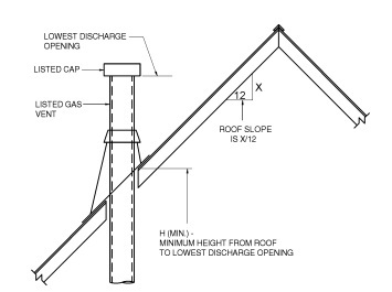
ROOF SLOPE H (min) ft Flat to 6/12 1.0 Over 6/12 to 7/12 1.25 Over 7/12 to 8/12 1.5 Over 8/12 to 9/12 2.0 Over 9/12 to 10/12 2.5 Over 10/12 to 11/12 3.25 Over 11/12 to 12/12 4.0 Over 12/12 to 14/12 5.0 Over 14/12 to 16/12 6.0 Over 16/12 to 18/12 7.0 Over 18/12 to 20/12 7.5 Over 20/12 to 21/12 8.0 For SI: 1 inch = 25.4 mm, 1 foot = 304.8 mm. FIGURE 503.6.4
TERMINATION LOCATIONS FOR GAS VENTS WITH
LISTED CAPS 12 INCHES OR LESS IN SIZE
AT LEAST 8 FEET FROM A VERTICAL WALL503.6.4.1 Decorative shrouds.
Decorative shrouds shall not be installed at the termination of gas vents except where such shrouds are listed for use with the specific gas venting system and are installed in accordance with manufacturer’s installation instructions.503.6.5 Minimum height.
A Type B or L gas vent shall terminate at least 5 feet (1524 mm) in vertical height above the highest connected appliance draft hood or flue collar. A Type B-W gas vent shall terminate at least 12 feet (3658 mm) in vertical height above the bottom of the wall furnace.503.6.6 Roof terminations.
Gas vents shall extend through the roof flashing, roof jack or roof thimble and terminate with a listed cap or listed roof assembly.503.6.7 Forced air inlets.
Gas vents shall terminate not less than 3 feet (914 mm) above any forced air inlet located within 10 feet (3048 mm).503.6.8 Exterior wall penetrations.
A gas vent extending through an exterior wall shall not terminate adjacent to the wall or below eaves or parapets, except as provided in Sections 503.2.3 and 503.3.3.503.6.9 Size of gas vents.
Venting systems shall be sized and constructed in accordance with Section 504 or other approved engineering methods and the gas vent and appliance manufacturer’s installation instructions.503.6.9.1 Category I appliances.
The sizing of natural draft venting systems serving one or more listed appliances equipped with a draft hood or appliances listed for use with Type B gas vent, installed in a single story of a building, shall be in accordance with one of the following methods:1. The provisions of Section 504.
2. For sizing an individual gas vent for a single draft-hood-equipped appliance, the effective area of the vent connector and the gas vent shall be not less than the area of the appliance draft hood outlet, nor greater than four times the draft hood outlet area.
3. For sizing a gas vent connected to two appliances with draft hoods, the effective area of the vent shall be not less than the area of the larger draft hood outlet plus 50 percent of the area of the smaller draft hood outlet, nor greater than four times the smaller draft hood outlet area.
4. Approved engineering practices.
503.6.9.2 Vent offsets.
Type B and L vents sized in accordance with Item 2 or 3 of Section 503.6.9.1 shall extend in a generally vertical direction with offsets not exceeding 45 degrees (0.79 rad), except that a vent system having not more than one 60-degree (1.04 rad) offset shall be permitted. Any angle greater than 45 degrees (0.79 rad) from the vertical is considered horizontal. The total horizontal distance of a vent plus the horizontal vent connector serving draft hood-equipped appliances shall be not greater than 75 percent of the vertical height of the vent.503.6.9.3 Category II, III and IV appliances.
The sizing of gas vents for Category II, III and IV appliances shall be in accordance with the appliance manufacturer’s instructions.503.6.9.4 Mechanical draft.
Chimney venting systems using mechanical draft shall be sized in accordance with approved engineering methods.503.6.10 Gas vents serving appliances on more than one floor.
A common vent shall be permitted in multistory installations to vent Category I appliances located on more than one floor level, provided that the venting system is designed and installed in accordance with approved engineering methods. For the purpose of this section, crawl spaces, basements and attics shall be considered as floor levels.503.6.10.1 Appliance separation.
All appliances connected to the common vent shall be located in rooms separated from occupiable space. Each of these rooms shall have provisions for an adequate supply of combustion, ventilation and dilution air that is not supplied from an occupiable space.Deleted
503.6.10.2 Sizing.
The size of the connectors and common segments of multistory venting systems for appliances listed for use with Type B double-wall gas vents shall be in accordance with Table 504.3(1), provided that:1. The available total height (H) for each segment of a multistory venting system is the vertical distance between the level of the highest draft hood outlet or flue collar on that floor and the centerline of the next highest interconnection tee.
2. The size of the connector for a segment is determined from the appliance input rating and available connector rise, and shall not be smaller than the draft hood outlet or flue collar size.
3. The size of the common vertical segment, and of the interconnection tee at the base of that segment, shall be based on the total appliance input rating entering that segment and its available total height.
503.6.11 Support of gas vents.
Gas vents shall be supported and spaced in accordance with the manufacturer’s installation instructions.503.6.12 Marking.
In those localities where solid and liquid fuels are used extensively, gas vents shall be permanently identified by a label attached to the wall or ceiling at a point where the vent connector enters the gas vent. The determination of where such localities exist shall be made by the code official. The label shall read:“This gas vent is for appliances that burn gas. Do not connect to solid or liquid fuel-burning appliances or incinerators.”
503.6.13 Fastener penetrations.
Screws, rivets and other fasteners shall not penetrate the inner wall of double-wall gas vents, except at the transition from an appliance draft hood outlet, a flue collar or a single-wall metal connector to a double-wall vent.503.7 Single-wall metal pipe.
Single-wall metal pipe vents shall comply with Sections 503.7.1 through 503.7.13.503.7.1 Construction.
Single-wall metal pipe shall be constructed of galvanized sheet steel not less than 0.0304 inch (0.7 mm) thick, or other approved, noncombustible, corrosion-resistant material.503.7.2 Cold climate.
Uninsulated single-wall metal pipe shall not be used outdoors for venting appliances in regions where the 99-percent winter design temperature is below 32°F (0°C).503.7.3 Termination.
Single-wall metal pipe shall terminate at least 5 feet (1524 mm) in vertical height above the highest connected appliance draft hood outlet or flue collar. Single-wall metal pipe shall extend at least 2 feet (610 mm) above the highest point where it passes through a roof of a building and at least 2 feet (610 mm) higher than any portion of a building within a horizontal distance of 10 feet (3048 mm). An approved cap or roof assembly shall be attached to the terminus of a single-wall metal pipe.503.7.4 Limitations of use.
Single-wall metal pipe shall be used only for runs directly from the space in which the appliance is located through the roof or exterior wall to the outdoor atmosphere.503.7.5 Roof penetrations.
A pipe passing through a roof shall extend without interruption through the roof flashing, roof jack or roof thimble. Where a single-wall metal pipe passes through a roof constructed of combustible material, a noncombustible, nonventilating thimble shall be used at the point of passage. The thimble shall extend at least 18 inches (457 mm) above and 6 inches (152 mm) below the roof with the annular space open at the bottom and closed only at the top. The thimble shall be sized in accordance with Section 503.7.7.503.7.6 Installation.
Single-wall metal pipe shall not originate in any unoccupied attic or concealed space and shall not pass through any attic, inside wall, concealed space or floor. The installation of a single-wall metal pipe through an exterior combustible wall shall comply with Section 503.7.7.503.7.7 Single-wall penetrations of combustible walls.
A single-wall metal pipe shall not pass through a combustible exterior wall unless guarded at the point of passage by a ventilated metal thimble not smaller than the following:1. For listed appliances with draft hoods and appliances listed for use with Type B gas vents, the thimble shall be not less than 4 inches (102 mm) larger in diameter than the metal pipe. Where there is a run of not less than 6 feet (1829 mm) of metal pipe in the open between the draft hood outlet and the thimble, the thimble shall be permitted to be not less than 2 inches (51 mm) larger in diameter than the metal pipe.
2. For unlisted appliances having draft hoods, the thimble shall be not less than 6 inches (152 mm) larger in diameter than the metal pipe.
3. For residential and low-heat appliances, the thimble shall be not less than 12 inches (305 mm) larger in diameter than the metal pipe.
Exception: In lieu of thimble protection, all combustible material in the wall shall be removed a sufficient distance from the metal pipe to provide the specified clearance from such metal pipe to combustible material. Any material used to close up such opening shall be noncombustible.
503.7.8 Clearances.
Minimum clearances from single-wall metal pipe to combustible material shall be in accordance with Table 503.10.5. The clearance from single-wall metal pipe to combustible materialshall be permitted to be reduced where the combustible material is protected as specified for vent connectors in Table 308.2.503.7.9 Size of single-wall metal pipe.
A venting system constructed of single-wall metal pipe shall be sized in accordance with one of the following methods and the appliance manufacturer’s instructions:1. For a draft hood-equipped appliance, in accordance with IFGC Section 504.
2. For a venting system for a single appliance with a draft hood, the areas of the connector and the pipe each shall be not less than the area of the appliance flue collar or draft hood outlet, whichever is smaller. The vent area shall not be greater than four times the draft hood outlet area.
3. Other approved engineering methods.
503.7.10 Pipe geometry.
Any shaped single-wall metal pipe shall be permitted to be used, provided that its equivalent effective area is equal to the effective area of the round pipe for which it is substituted, and provided that the minimum internal dimension of the pipe is not less than 2 inches (51 mm).503.7.11 Termination capacity.
The vent cap or a roof assembly shall have a venting capacity of not less than that of the pipe to which it is attached.503.7.12 Support of single-wall metal pipe.
All portions of single-wall metal pipe shall be supported for the design and weight of the material employed.503.7.13 Marking.
Single-wall metal pipe shall comply with the marking provisions of Section 503.6.12.503.8 Venting system termination location.
The location of venting system terminations shall comply with the following (see Appendix C):1. A mechanical draft venting system shall terminate at least 3 feet (914 mm) above any forced-air inlet located within 10 feet (3048 mm).
Exceptions:
1. This provision shall not apply to the combustion air intake of a direct-vent appliance.
2. This provision shall not apply to the separation of the integral outdoor air inlet and flue gas discharge of listed outdoor appliances.
2. A mechanical draft venting system, excluding direct-vent appliances, shall terminate at least 4 feet (1219 mm) below, 4 feet (1219 mm) horizontally from, or 1 foot (305 mm) above any door, operable window or gravity air inlet into any building. The bottom of the vent terminal shall be located at least 12 inches (305 mm) above finished ground level.
3. The vent terminal of a direct-vent appliance with an input of 10,000 Btu per hour (3 kW) or less shall be located at least 6 inches (152 mm) from any air opening into a building, and such an appliance with an input over 10,000 Btu per hour (3 kW) but not over 50,000 Btu per hour (14.7 kW) shall be installed with a 9-inch (230 mm) vent termination clearance, and an appliance with an input over 50,000 Btu/h (14.7 kW) shall have at least a 12-inch (305 mm) vent termination clearance. The bottom of the vent terminal and the air intake shall be located at least 12 inches (305 mm) above finished ground level.
4. Through-the-wall vents for Category II and IV appliances and noncategorized condensing appliances shall not terminate over public walkways or over an area where condensate or vapor could create a nuisance or hazard or could be detrimental to the operation of regulators, relief valves or other equipment. Where local experience indicates that condensate is a problem with Category I and III appliances, this provision shall also apply. Drains for condensate shall be installed in accordance with the appliance and vent manufacturers’ instructions.
503.9 Condensation drainage.
Provisions shall be made to collect and dispose of condensate from venting systems serving Category II and IV appliances and noncategorized condensing appliances in accordance with Section 503.8, Item 4. Where local experience indicates that condensation is a problem, provision shall be made to drain off and dispose of condensate from venting systems serving Category I and III appliances in accordance with Section 503.8, Item 4.503.10 Vent connectors for Category I appliances.
Vent connectors for Category I appliances shall comply with Sections 503.10.1 through 503.10.14.503.10.1 Where required.
A vent connector shall be used to connect an appliance to a gas vent, chimney or single-wall metal pipe, except where the gas vent, chimney or single-wall metal pipe is directly connected to the appliance.503.10.2 Materials.
Vent connectors shall be constructed in accordance with Sections 503.10.2.1 through 503.10.2.5.503.10.2.1 General.
A vent connector shall be made of noncombustible corrosion-resistant material capable of withstanding the vent gas temperature produced by the appliance and of sufficient thickness to withstand physical damage.503.10.2.2 Vent connectors located in unconditioned areas.
Where the vent connector used for an appliance having a draft hood or a Category I appliance is located in or passes through attics, crawl spaces or other unconditioned spaces, that portion of the vent connector shall be listed Type B, Type L or listed vent material having equivalent insulation properties.Exception: Single-wall metal pipe located within the exterior walls of the building in areas having a local 99-percent winter design temperature of 5°F (-15°C) or higher shall be permitted to be used in unconditioned spaces other than attics and crawl spaces.
503.10.2.3 Residential-type appliance connectors.
Where vent connectors for residential-type appliances are not installed in attics or other unconditioned spaces, connectors for listed appliances having draft hoods, appliances having draft hoods and equipped with listed conversion burners and Category I appliances shall be one of the following:1. Type B or L vent material;
2. Galvanized sheet steel not less than 0.018 inch (0.46 mm) thick;
3. Aluminum (1100 or 3003 alloy or equivalent) sheet not less than 0.027 inch (0.69 mm) thick;
4. Stainless steel sheet not less than 0.012 inch (0.31 mm) thick;
5. Smooth interior wall metal pipe having resistance to heat and corrosion equal to or greater than that of Item 2, 3 or 4 above; or
6. A listed vent connector.
Vent connectors shall not be covered with insulation.
Exception: Listed insulated vent connectors shall be installed in accordance with the manufacturer’s installation instructions.
503.10.2.4 Low-heat equipment.
A vent connector for a nonresidential, low-heat appliance shall be a factory-built chimney section or steel pipe having resistance to heat and corrosion equivalent to that for the appropriate galvanized pipe as specified in Table 503.10.2.4. Factory-built chimney sections shall be joined together in accordance with the chimney manufacturer’s instructions.TABLE 503.10.2.4
MINIMUM THICKNESS FOR GALVANIZED STEEL VENT CONNECTORS FOR LOW-HEAT APPLIANCESDIAMETER OF CONNECTOR
(inches)MINIMUM THICKNESS
(inch)Less than 6 0.019 6 to less than 10 0.023 10 to 12 inclusive 0.029 14 to 16 inclusive 0.034 Over 16 0.056 For SI: 1 inch = 25.4 mm. 503.10.2.5 Medium-heat appliances.
Vent connectors for medium-heat appliances shall be constructed of factory-built medium-heat chimney sections or steel of a thickness not less than that specified in Table 503.10.2.5 and shall comply with the following:1. A steel vent connector for an appliance with a vent gas temperature in excess of 1,000°F (538°C) measured at the entrance to the connector shall be lined with medium-duty fire brick (ASTM C64, Type F), or the equivalent.
2. The lining shall be at least 21/2 inches (64 mm) thick for a vent connector having a diameter or greatest cross-sectional dimension of 18 inches (457 mm) or less.
3. The lining shall be at least 41/2 inches (114 mm) thick laid on the 41/2-inch (114 mm) bed for a vent connector having a diameter or greatest cross-sectional dimension greater than 18 inches (457 mm).
4. Factory-built chimney sections, if employed, shall be joined together in accordance with the chimney manufacturer’s instructions.
TABLE 503.10.2.5
MINIMUM THICKNESS FOR STEEL VENT
CONNECTORS FOR MEDIUM-HEAT APPLIANCESVENT CONNECTOR SIZE Diameter
(inches)Area
(square inches)MINIMUM THICKNESS
(inch)Up to 14 Up to 154 0.053 Over 14 to 16 154 to 201 0.067 Over 16 to 18 201 to 254 0.093 Over 18 Larger than 254 0.123 For SI: 1 inch = 25.4 mm, 1 square inch = 645.16 mm2. 503.10.3 Size of vent connector.
Vent connectors shall be sized in accordance with Sections 503.10.3.1 through 503.10.3.5.503.10.3.1 Single draft hood and fan-assisted.
A vent connector for an appliance with a single draft hood or for a Category I fan-assisted combustion system appliance shall be sized and installed in accordance with Section 504 or other approved engineering methods.503.10.3.2 Multiple draft hood.
For a single appliance having more than one draft hood outlet or flue collar, the manifold shall be constructed according to the instructions of the appliance manufacturer. Where there are no instructions, the manifold shall be designed and constructed in accordance with approved engineering practices. As an alternate method, the effective area of the manifold shall equal the combined area of the flue collars or draft hood outlets and the vent connectors shall have a minimum 1-foot (305 mm) rise.503.10.3.3 Multiple appliances.
Where two or more appliances are connected to a common vent or chimney, each vent connector shall be sized in accordance with Section 504 or other approved engineering methods.As an alternative method applicable only when all of the appliances are draft hood equipped, each vent connector shall have an effective area not less than the area of the draft hood outlet of the appliance to which it is connected.
503.10.3.4 Common connector/manifold.
Where two or more appliances are vented through a common vent connector or vent manifold, the common vent connector or vent manifold shall be located at the highest level consistent with available headroom and the required clearance to combustible materials and shall be sized in accordance with Section 504 or other approved engineering methods.As an alternate method applicable only where there are two draft hood-equipped appliances, the effective area of the common vent connector or vent manifold and all junction fittings shall be not less than the area of the larger vent connector plus 50 percent of the area of the smaller flue collar outlet.
503.10.3.5 Size increase.
Where the size of a vent connector is increased to overcome installation limitations and obtain connector capacity equal to the appliance input, the size increase shall be made at the appliance draft hood outlet.503.10.4 Two or more appliances connected to a single vent or chimney.
Where two or more vent connectors enter a common vent, chimney flue or single-wall metal pipe, the smaller connector shall enter at the highest level consistent with the available headroom or clearance to combustible material. Vent connectors serving Category I appliances shall not be connected to any portion of a mechanical draft system operating under positive static pressure, such as those serving Category III or IV appliances.503.10.4.1 Two or more openings.
Where two or more openings are provided into one chimney flue or vent, the openings shall be at different levels, or the connectors shall be attached to the vertical portion of the chimney or vent at an angle of 45 degrees (0.79 rad) or less relative to the vertical.503.10.5 Clearance.
Minimum clearances from vent connectors to combustible material shall be in accordance with Table 503.10.5.Exception: The clearance between a vent connector and combustible material shall be permitted to be reduced where the combustible material is protected as specified for vent connectors in Table 308.2.
Deleted
TABLE 503.10.5a
CLEARANCES FOR CONNECTORSAPPLIANCE MINIMUM DISTANCE FROM COMBUSTIBLE MATERIAL Listed Type B gas
vent materialListed Type L vent
materialSingle-wall
metal pipeFactory-built
chimney sectionsListed appliances with draft hoods and appliances listed for use with
Type B gas ventsAs listed As listed 6 inches As listed Residential boilers and furnaces with listed gas conversion burner and
with draft hood6 inches 6 inches 9 inches As listed Residential appliances listed for use with Type L vents Not permitted As listed 9 inches As listed Listed gas-fired toilets Not permitted As listed As listed As listed Unlisted residential appliances with draft hood Not permitted 6 inches 9 inches As listed Residential and low-heat appliances other than above Not permitted 9 inches 18 inches As listed Medium-heat appliances Not permitted Not permitted 36 inches As listed For SI: 1 inch = 25.4 mm. a. These clearances shall apply unless the manufacturer’s installation instructions for a listed appliance or connector specify different clearances, in which case the listed clearances shall apply. 503.10.6 Joints.
Joints between sections of connector piping and connections to flue collars and draft hood outlets shall be fastened by one of the following methods:1. Sheet metal screws.
2. Vent connectors of listed vent material assembled and connected to flue collars or draft hood outlets in accordance with the manufacturers’ instructions.
3. Other approved means.
503.10.7 Slope.
A vent connector shall be installed without dips or sags and shall slope upward toward the vent or chimney at least 1/4 inch per foot (21 mm/m).Exception: Vent connectors attached to a mechanical draft system installed in accordance with the appliance and draft system manufacturers’ instructions.
503.10.8 Length of vent connector.
The maximum horizontal length of a single-wall connector shall be 75 percent of the height of the chimney or vent except for engineered systems. The maximum horizontal length of a Type B double-wall connector shall be 100 percent of the height of the chimney or vent except for engineered systems.503.10.9 Support.
A vent connector shall be supported for the design and weight of the material employed to maintain clearances and prevent physical damage and separation of joints.503.10.10 Chimney connection.
Where entering a flue in a masonry or metal chimney, the vent connector shall be installed above the extreme bottom to avoid stoppage. Where a thimble or slip joint is used to facilitate removal of the connector, the connector shall be firmly attached to or inserted into the thimble or slip joint to prevent the connector from falling out. Means shall be employed to prevent the connector from entering so far as to restrict the space between its end and the opposite wall of the chimney flue (see Section 501.9).503.10.11 Inspection.
The entire length of a vent connector shall be provided with ready access for inspection, cleaning and replacement.503.10.12 Fireplaces.
A vent connector shall not be connected to a chimney flue serving a fireplace unless the fireplace flue opening is permanently sealed.503.10.13 Passage through ceilings, floors or walls.
Single-wall metal pipe connectors shall not pass through any wall, floor or ceiling except as permitted by Section 503.7.4.503.10.14 Medium-heat connectors.
Vent connectors for medium-heat appliances shall not pass through walls or partitions constructed of combustible material.503.11 Vent connectors for Category II, III and IV appliances.
Vent connectors for Category II, III and IV appliances shall be as specified for the venting systems in accordance with Section 503.4.503.12 Draft hoods and draft controls.
The installation of draft hoods and draft controls shall comply with Sections 503.12.1 through 503.12.7.503.12.1 Appliances requiring draft hoods.
Vented appliances shall be installed with draft hoods.Exception: Dual oven-type combination ranges; direct-vent appliances; fan-assisted combustion system appliances; appliances requiring chimney draft for operation; single firebox boilers equipped with conversion burners with inputs greater than 400,000 Btu per hour (117 kW); appliances equipped with blast, power or pressure burners that are not listed for use with draft hoods; and appliances designed for forced venting.
503.12.2 Installation.
A draft hood supplied with or forming a part of a listed vented appliance shall be installed without alteration, exactly as furnished and specified by the appliance manufacturer.503.12.2.1 Draft hood required.
If a draft hood is not supplied by the appliance manufacturer where one is required, a draft hood shall be installed, shall be of a listed or approved type and, in the absence of other instructions, shall be of the same size as the appliance flue collar. Where a draft hood is required with a conversion burner, it shall be of a listed or approved type.503.12.2.2 Special design draft hood.
Where it is determined that a draft hood of special design is needed or preferable for a particular installation, the installation shall be in accordance with the recommendations of the appliance manufacturer and shall be approved.503.12.3 Draft control devices.
Where a draft control device is part of the appliance or is supplied by the appliance manufacturer, it shall be installed in accordance with the manufacturer’s instructions. In the absence of manufacturer’s instructions, the device shall be attached to the flue collar of the appliance or as near to the appliance as practical.503.12.4 Additional devices.
Appliances requiring a controlled chimney draft shall be permitted to be equipped with a listed double-acting barometric-draft regulator installed and adjusted in accordance with the manufacturer’s instructions.503.12.5 Location.
Draft hoods and barometric draft regulators shall be installed in the same room or enclosure as the appliance in such a manner as to prevent any difference in pressure between the hood or regulator and the combustion air supply.503.12.6 Positioning.
Draft hoods and draft regulators shall be installed in the position for which they were designed with reference to the horizontal and vertical planes and shall be located so that the relief opening is not obstructed by any part of the appliance or adjacent construction. The appliance and its draft hood shall be located so that the relief opening is accessible for checking vent operation.503.12.7 Clearance.
A draft hood shall be located so its relief opening is not less than 6 inches (152 mm) from any surface except that of the appliance it serves and the venting system to which the draft hood is connected. Where a greater or lesser clearance is indicated on the appliance label, the clearance shall be not less than that specified on the label. Such clearances shall not be reduced.503.13 Manually operated dampers.
A manually operated damper shall not be placed in the vent connector for any appliance. Fixed baffles shall not be classified as manually operated dampers.503.14 Automatically operated vent dampers.
An automatically operated vent damper shall be of a listed type.503.15 Obstructions.
Devices that retard the flow of vent gases shall not be installed in a vent connector, chimney or vent. The following shall not be considered as obstructions:1. Draft regulators and safety controls specifically listed for installation in venting systems and installed in accordance with the manufacturer’s installation instructions.
2. Approved draft regulators and safety controls that are designed and installed in accordance with approved engineering methods.
3. Listed heat reclaimers and automatically operated vent dampers installed in accordance with the manufacturer’s installation instructions.
4. Approved economizers, heat reclaimers and recuperators installed in venting systems of appliances not required to be equipped with draft hoods, provided that the appliance manufacturer’s instructions cover the installation of such a device in the venting system and performance in accordance with Sections 503.3 and 503.3.1 is obtained.
5. Vent dampers serving listed appliances installed in accordance with Sections 504.2.1 and 504.3.1 or other approved engineering methods.
503.16 Outside wall penetrations.
Where vents, including those for direct-vent appliances, penetrate outside walls of buildings, the annular spaces around such penetrations shall be permanently sealed using approvedmaterials to prevent entry of combustion products into the building.
SECTION 504 (IFGS)
SIZING OF CATEGORY I APPLIANCE
VENTING SYSTEMS
504.1 Definitions.
The following definitions apply to the tables in this section.
APPLIANCE CATEGORIZED VENT DIAMETER/AREA. The minimum vent area/diameter permissible for Category I appliances to maintain a nonpositive vent static pressure when tested in accordance with nationally recognized standards.
FAN-ASSISTED COMBUSTION SYSTEM. An appliance equipped with an integral mechanical means to either draw or force products of combustion through the combustion chamber or heat exchanger.
FAN Min. The minimum input rating of a Category I fan-assisted appliance attached to a vent or connector.
FAN Max. The maximum input rating of a Category I fan-assisted appliance attached to a vent or connector.
NAT Max. The maximum input rating of a Category I draft-hood-equipped appliance attached to a vent or connector.
FAN + FAN. The maximum combined appliance input rating of two or more Category I fan-assisted appliances attached to the common vent.
FAN + NAT. The maximum combined appliance input rating of one or more Category I fan-assisted appliances and one or more Category I draft-hood-equipped appliances attached to the common vent.
NA. Vent configuration is not allowed due to potential for condensate formation or pressurization of the venting system, or not applicable due to physical or geometric restraints.
NAT + NAT. The maximum combined appliance input rating of two or more Category I draft-hood-equipped appliances attached to the common vent.
504.2 Application of single-appliance vent Tables 504.2(1) through 504.2(6).
The application of Tables 504.2(1) through 504.2(6) shall be subject to the requirements of Sections 504.2.1 through 504.2.17.
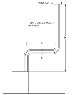
| For SI: 1 foot = 304.8 mm, 1 British thermal unit per hour = 0.2931 W. Table 504.2(1) is used when sizing Type B double-wall gas vent connected directly to the appliance. Note: The appliance may be either Category I draft hood equipped or fanassisted type. |
FIGURE B-1
TYPE B DOUBLE-WALL VENT SYSTEM SERVING A SINGLE
APPLIANCE WITH A TYPE B DOUBLE-WALL VENT
TABLE 504.2(1)
TYPE B DOUBLE-WALL GAS VENT
| Number of Appliances | Single |
| Appliance Type | Category I |
| Appliance Vent Connection | Connected directly to vent |
| HEIGHT (H) (feet) |
LATERAL (L) (feet) |
VENT DIAMETER—(D) inches | ||||||||||||||||||||
| 3 | 4 | 5 | 6 | 7 | 8 | 9 | ||||||||||||||||
| APPLIANCE INPUT RATING IN THOUSANDS OF BTU/H | ||||||||||||||||||||||
| FAN | NAT | FAN | NAT | FAN | NAT | FAN | NAT | FAN | NAT | FAN | NAT | FAN | NAT | |||||||||
| Min | Max | Max | Min | Max | Max | Min | Max | Max | Min | Max | Max | Min | Max | Max | Min | Max | Max | Min | Max | Max | ||
| 6 | 0 | 0 | 78 | 46 | 0 | 152 | 86 | 0 | 251 | 141 | 0 | 375 | 205 | 0 | 524 | 285 | 0 | 698 | 370 | 0 | 897 | 470 |
| 2 | 13 | 51 | 36 | 18 | 97 | 67 | 27 | 157 | 105 | 32 | 232 | 157 | 44 | 321 | 217 | 53 | 425 | 285 | 63 | 543 | 370 | |
| 4 | 21 | 49 | 34 | 30 | 94 | 64 | 39 | 153 | 103 | 50 | 227 | 153 | 66 | 316 | 211 | 79 | 419 | 279 | 93 | 536 | 362 | |
| 6 | 25 | 46 | 32 | 36 | 91 | 61 | 47 | 149 | 100 | 59 | 223 | 149 | 78 | 310 | 205 | 93 | 413 | 273 | 110 | 530 | 354 | |
| 8 | 0 | 0 | 84 | 50 | 0 | 165 | 94 | 0 | 276 | 155 | 0 | 415 | 235 | 0 | 583 | 320 | 0 | 780 | 415 | 0 | 1,006 | 537 |
| 2 | 12 | 57 | 40 | 16 | 109 | 75 | 25 | 178 | 120 | 28 | 263 | 180 | 42 | 365 | 247 | 50 | 483 | 322 | 60 | 619 | 418 | |
| 5 | 23 | 53 | 38 | 32 | 103 | 71 | 42 | 171 | 115 | 53 | 255 | 173 | 70 | 356 | 237 | 83 | 473 | 313 | 99 | 607 | 407 | |
| 8 | 28 | 49 | 35 | 39 | 98 | 66 | 51 | 164 | 109 | 64 | 247 | 165 | 84 | 347 | 227 | 99 | 463 | 303 | 117 | 596 | 396 | |
| 10 | 0 | 0 | 88 | 53 | 0 | 175 | 100 | 0 | 295 | 166 | 0 | 447 | 255 | 0 | 631 | 345 | 0 | 847 | 450 | 0 | 1,096 | 585 |
| 2 | 12 | 61 | 42 | 17 | 118 | 81 | 23 | 194 | 129 | 26 | 289 | 195 | 40 | 402 | 273 | 48 | 533 | 355 | 57 | 684 | 457 | |
| 5 | 23 | 57 | 40 | 32 | 113 | 77 | 41 | 187 | 124 | 52 | 280 | 188 | 68 | 392 | 263 | 81 | 522 | 346 | 95 | 671 | 446 | |
| 10 | 30 | 51 | 36 | 41 | 104 | 70 | 54 | 176 | 115 | 67 | 267 | 175 | 88 | 376 | 245 | 104 | 504 | 330 | 122 | 651 | 427 | |
| 15 | 0 | 0 | 94 | 58 | 0 | 191 | 112 | 0 | 327 | 187 | 0 | 502 | 285 | 0 | 716 | 390 | 0 | 970 | 525 | 0 | 1,263 | 682 |
| 2 | 11 | 69 | 48 | 15 | 136 | 93 | 20 | 226 | 150 | 22 | 339 | 225 | 38 | 475 | 316 | 45 | 633 | 414 | 53 | 815 | 544 | |
| 5 | 22 | 65 | 45 | 30 | 130 | 87 | 39 | 219 | 142 | 49 | 330 | 217 | 64 | 463 | 300 | 76 | 620 | 403 | 90 | 800 | 529 | |
| 10 | 29 | 59 | 41 | 40 | 121 | 82 | 51 | 206 | 135 | 64 | 315 | 208 | 84 | 445 | 288 | 99 | 600 | 386 | 116 | 777 | 507 | |
| 15 | 35 | 53 | 37 | 48 | 112 | 76 | 61 | 195 | 128 | 76 | 301 | 198 | 98 | 429 | 275 | 115 | 580 | 373 | 134 | 755 | 491 | |
| 20 | 0 | 0 | 97 | 61 | 0 | 202 | 119 | 0 | 349 | 202 | 0 | 540 | 307 | 0 | 776 | 430 | 0 | 1,057 | 575 | 0 | 1,384 | 752 |
| 2 | 10 | 75 | 51 | 14 | 149 | 100 | 18 | 250 | 166 | 20 | 377 | 249 | 33 | 531 | 346 | 41 | 711 | 470 | 50 | 917 | 612 | |
| 5 | 21 | 71 | 48 | 29 | 143 | 96 | 38 | 242 | 160 | 47 | 367 | 241 | 62 | 519 | 337 | 73 | 697 | 460 | 86 | 902 | 599 | |
| 10 | 28 | 64 | 44 | 38 | 133 | 89 | 50 | 229 | 150 | 62 | 351 | 228 | 81 | 499 | 321 | 95 | 675 | 443 | 112 | 877 | 576 | |
| 15 | 34 | 58 | 40 | 46 | 124 | 84 | 59 | 217 | 142 | 73 | 337 | 217 | 94 | 481 | 308 | 111 | 654 | 427 | 129 | 853 | 557 | |
| 20 | 48 | 52 | 35 | 55 | 116 | 78 | 69 | 206 | 134 | 84 | 322 | 206 | 107 | 464 | 295 | 125 | 634 | 410 | 145 | 830 | 537 | |
(continued)
TABLE 504.2(1)—continued
TYPE B DOUBLE-WALL GAS VENT
| Number of Appliances | Single |
| Appliance Type | Category I |
| Appliance Vent Connection | Connected directly to vent |
| HEIGHT (H) (feet) |
LATERAL (L) (feet) |
VENT DIAMETER—(D) inches | ||||||||||||||||||||
| 3 | 4 | 5 | 6 | 7 | 8 | 9 | ||||||||||||||||
| APPLIANCE INPUT RATING IN THOUSANDS OF BTU/H | ||||||||||||||||||||||
| FAN | NAT | FAN | NAT | FAN | NAT | FAN | NAT | FAN | NAT | FAN | NAT | FAN | NAT | |||||||||
| Min | Max | Max | Min | Max | Max | Min | Max | Max | Min | Max | Max | Min | Max | Max | Min | Max | Max | Min | Max | Max | ||
| 30 | 0 | 0 | 100 | 64 | 0 | 213 | 128 | 0 | 374 | 220 | 0 | 587 | 336 | 0 | 853 | 475 | 0 | 1,173 | 650 | 0 | 1,548 | 855 |
| 2 | 9 | 81 | 56 | 13 | 166 | 112 | 14 | 283 | 185 | 18 | 432 | 280 | 27 | 613 | 394 | 33 | 826 | 535 | 42 | 1,072 | 700 | |
| 5 | 21 | 77 | 54 | 28 | 160 | 108 | 36 | 275 | 176 | 45 | 421 | 273 | 58 | 600 | 385 | 69 | 811 | 524 | 82 | 1,055 | 688 | |
| 10 | 27 | 70 | 50 | 37 | 150 | 102 | 48 | 262 | 171 | 59 | 405 | 261 | 77 | 580 | 371 | 91 | 788 | 507 | 107 | 1,028 | 668 | |
| 15 | 33 | 64 | NA | 44 | 141 | 96 | 57 | 249 | 163 | 70 | 389 | 249 | 90 | 560 | 357 | 105 | 765 | 490 | 124 | 1,002 | 648 | |
| 20 | 56 | 58 | NA | 53 | 132 | 90 | 66 | 237 | 154 | 80 | 374 | 237 | 102 | 542 | 343 | 119 | 743 | 473 | 139 | 977 | 628 | |
| 30 | NA | NA | NA | 73 | 113 | NA | 88 | 214 | NA | 104 | 346 | 219 | 131 | 507 | 321 | 149 | 702 | 444 | 171 | 929 | 594 | |
| 50 | 0 | 0 | 101 | 67 | 0 | 216 | 134 | 0 | 397 | 232 | 0 | 633 | 363 | 0 | 932 | 518 | 0 | 1,297 | 708 | 0 | 1,730 | 952 |
| 2 | 8 | 86 | 61 | 11 | 183 | 122 | 14 | 320 | 206 | 15 | 497 | 314 | 22 | 715 | 445 | 26 | 975 | 615 | 33 | 1,276 | 813 | |
| 5 | 20 | 82 | NA | 27 | 177 | 119 | 35 | 312 | 200 | 43 | 487 | 308 | 55 | 702 | 438 | 65 | 960 | 605 | 77 | 1,259 | 798 | |
| 10 | 26 | 76 | NA | 35 | 168 | 114 | 45 | 299 | 190 | 56 | 471 | 298 | 73 | 681 | 426 | 86 | 935 | 589 | 101 | 1,230 | 773 | |
| 15 | 59 | 70 | NA | 42 | 158 | NA | 54 | 287 | 180 | 66 | 455 | 288 | 85 | 662 | 413 | 100 | 911 | 572 | 117 | 1,203 | 747 | |
| 20 | NA | NA | NA | 50 | 149 | NA | 63 | 275 | 169 | 76 | 440 | 278 | 97 | 642 | 401 | 113 | 888 | 556 | 131 | 1,176 | 722 | |
| 30 | NA | NA | NA | 69 | 131 | NA | 84 | 250 | NA | 99 | 410 | 259 | 123 | 605 | 376 | 141 | 844 | 522 | 161 | 1,125 | 670 | |
| 100 | 0 | NA | NA | NA | 0 | 218 | NA | 0 | 407 | NA | 0 | 665 | 400 | 0 | 997 | 560 | 0 | 1,411 | 770 | 0 | 1,908 | 1,040 |
| 2 | NA | NA | NA | 10 | 194 | NA | 12 | 354 | NA | 13 | 566 | 375 | 18 | 831 | 510 | 21 | 1,155 | 700 | 25 | 1,536 | 935 | |
| 5 | NA | NA | NA | 26 | 189 | NA | 33 | 347 | NA | 40 | 557 | 369 | 52 | 820 | 504 | 60 | 1,141 | 692 | 71 | 1,519 | 926 | |
| 10 | NA | NA | NA | 33 | 182 | NA | 43 | 335 | NA | 53 | 542 | 361 | 68 | 801 | 493 | 80 | 1,118 | 679 | 94 | 1,492 | 910 | |
| 15 | NA | NA | NA | 40 | 174 | NA | 50 | 321 | NA | 62 | 528 | 353 | 80 | 782 | 482 | 93 | 1,095 | 666 | 109 | 1,465 | 895 | |
| 20 | NA | NA | NA | 47 | 166 | NA | 59 | 311 | NA | 71 | 513 | 344 | 90 | 763 | 471 | 105 | 1,073 | 653 | 122 | 1,438 | 880 | |
| 30 | NA | NA | NA | NA | NA | NA | 78 | 290 | NA | 92 | 483 | NA | 115 | 726 | 449 | 131 | 1,029 | 627 | 149 | 1,387 | 849 | |
| 50 | NA | NA | NA | NA | NA | NA | NA | NA | NA | 147 | 428 | NA | 180 | 651 | 405 | 197 | 944 | 575 | 217 | 1,288 | 787 | |
(continued)
TABLE 504.2(1)—continued
TYPE B DOUBLE-WALL GAS VENT
| Number of Appliances | Single |
| Appliance Type | Category I |
| Appliance Vent Connection | Connected directly to vent |
| HEIGHT (H) (feet) |
LATERAL (L) (feet) |
VENT DIAMETER—(D) inches | |||||||||||||||||||||||
| 10 | 12 | 14 | 16 | 18 | 20 | 22 | 24 | ||||||||||||||||||
| APPLIANCE INPUT RATING IN THOUSANDS OF BTU/H | |||||||||||||||||||||||||
| FAN | NAT | FAN | NAT | FAN | NAT | FAN | NAT | FAN | NAT | FAN | NAT | FAN | NAT | FAN | NAT | ||||||||||
| Min | Max | Max | Min | Max | Max | Min | Max | Max | Min | Max | Max | Min | Max | Max | Min | Max | Max | Min | Max | Max | Min | Max | Max | ||
| 6 | 0 | 0 | 1,121 | 570 | 0 | 1,645 | 850 | 0 | 2,267 | 1,170 | 0 | 2,983 | 1,530 | 0 | 3,802 | 1,960 | 0 | 4,721 | 2,430 | 0 | 5,737 | 2,950 | 0 | 6,853 | 3,520 |
| 2 | 75 | 675 | 455 | 103 | 982 | 650 | 138 | 1,346 | 890 | 178 | 1,769 | 1,170 | 225 | 2,250 | 1,480 | 296 | 2,782 | 1,850 | 360 | 3,377 | 2,220 | 426 | 4,030 | 2,670 | |
| 4 | 110 | 668 | 445 | 147 | 975 | 640 | 191 | 1,338 | 880 | 242 | 1,761 | 1,160 | 300 | 2,242 | 1,475 | 390 | 2,774 | 1,835 | 469 | 3,370 | 2,215 | 555 | 4,023 | 2,660 | |
| 6 | 128 | 661 | 435 | 171 | 967 | 630 | 219 | 1,330 | 870 | 276 | 1,753 | 1,150 | 341 | 2,235 | 1,470 | 437 | 2,767 | 1,820 | 523 | 3,363 | 2,210 | 618 | 4,017 | 2,650 | |
| 8 | 0 | 0 | 1,261 | 660 | 0 | 1,858 | 970 | 0 | 2,571 | 1,320 | 0 | 3,399 | 1,740 | 0 | 4,333 | 2,220 | 0 | 5,387 | 2,750 | 0 | 6,555 | 3,360 | 0 | 7,838 | 4,010 |
| 2 | 71 | 770 | 515 | 98 | 1,124 | 745 | 130 | 1,543 | 1,020 | 168 | 2,030 | 1,340 | 212 | 2,584 | 1,700 | 278 | 3,196 | 2,110 | 336 | 3,882 | 2,560 | 401 | 4,634 | 3,050 | |
| 5 | 115 | 758 | 503 | 154 | 1,110 | 733 | 199 | 1,528 | 1,010 | 251 | 2,013 | 1,330 | 311 | 2,563 | 1,685 | 398 | 3,180 | 2,090 | 476 | 3,863 | 2,545 | 562 | 4,612 | 3,040 | |
| 8 | 137 | 746 | 490 | 180 | 1,097 | 720 | 231 | 1,514 | 1,000 | 289 | 2,000 | 1,320 | 354 | 2,552 | 1,670 | 450 | 3,163 | 2,070 | 537 | 3,850 | 2,530 | 630 | 4,602 | 3,030 | |
| 10 | 0 | 0 | 1,377 | 720 | 0 | 2,036 | 1,060 | 0 | 2,825 | 1,450 | 0 | 3,742 | 1,925 | 0 | 4,782 | 2,450 | 0 | 5,955 | 3,050 | 0 | 7,254 | 3,710 | 0 | 8,682 | 4,450 |
| 2 | 68 | 852 | 560 | 93 | 1,244 | 850 | 124 | 1,713 | 1,130 | 161 | 2,256 | 1,480 | 202 | 2,868 | 1,890 | 264 | 3,556 | 2,340 | 319 | 4,322 | 2,840 | 378 | 5,153 | 3,390 | |
| 5 | 112 | 839 | 547 | 149 | 1,229 | 829 | 192 | 1,696 | 1,105 | 243 | 2,238 | 1,461 | 300 | 2,849 | 1,871 | 382 | 3,536 | 2,318 | 458 | 4,301 | 2,818 | 540 | 5,132 | 3,371 | |
| 10 | 142 | 817 | 525 | 187 | 1,204 | 795 | 238 | 1,669 | 1,080 | 298 | 2,209 | 1,430 | 364 | 2,818 | 1,840 | 459 | 3,504 | 2,280 | 546 | 4,268 | 2,780 | 641 | 5,099 | 3,340 | |
| 15 | 0 | 0 | 1,596 | 840 | 0 | 2,380 | 1,240 | 0 | 3,323 | 1,720 | 0 | 4,423 | 2,270 | 0 | 5,678 | 2,900 | 0 | 7,099 | 3,620 | 0 | 8,665 | 4,410 | 0 | 10,393 | 5,300 |
| 2 | 63 | 1,019 | 675 | 86 | 1,495 | 985 | 114 | 2,062 | 1,350 | 147 | 2,719 | 1,770 | 186 | 3,467 | 2,260 | 239 | 4,304 | 2,800 | 290 | 5,232 | 3,410 | 346 | 6,251 | 4,080 | |
| 5 | 105 | 1,003 | 660 | 140 | 1,476 | 967 | 182 | 2,041 | 1,327 | 229 | 2,696 | 1,748 | 283 | 3,442 | 2,235 | 355 | 4,278 | 2,777 | 426 | 5,204 | 3,385 | 501 | 6,222 | 4,057 | |
| 10 | 135 | 977 | 635 | 177 | 1,446 | 936 | 227 | 2,009 | 1,289 | 283 | 2,659 | 1,712 | 346 | 3,402 | 2,193 | 432 | 4,234 | 2,739 | 510 | 5,159 | 3,343 | 599 | 6,175 | 4,019 | |
| 15 | 155 | 953 | 610 | 202 | 1,418 | 905 | 257 | 1,976 | 1,250 | 318 | 2,623 | 1,675 | 385 | 3,363 | 2,150 | 479 | 4,192 | 2,700 | 564 | 5,115 | 3,300 | 665 | 6,129 | 3,980 | |
| 20 | 0 | 0 | 1,756 | 930 | 0 | 2,637 | 1,350 | 0 | 3,701 | 1,900 | 0 | 4,948 | 2,520 | 0 | 6,376 | 3,250 | 0 | 7,988 | 4,060 | 0 | 9,785 | 4,980 | 0 | 11,753 | 6,000 |
| 2 | 59 | 1,150 | 755 | 81 | 1,694 | 1,100 | 107 | 2,343 | 1,520 | 139 | 3,097 | 2,000 | 175 | 3,955 | 2,570 | 220 | 4,916 | 3,200 | 269 | 5,983 | 3,910 | 321 | 7,154 | 4,700 | |
| 5 | 101 | 1,133 | 738 | 135 | 1,674 | 1,079 | 174 | 2,320 | 1,498 | 219 | 3,071 | 1,978 | 270 | 3,926 | 2,544 | 337 | 4,885 | 3,174 | 403 | 5,950 | 3,880 | 475 | 7,119 | 4,662 | |
| 10 | 130 | 1,105 | 710 | 172 | 1,641 | 1,045 | 220 | 2,282 | 1,460 | 273 | 3,029 | 1,940 | 334 | 3,880 | 2,500 | 413 | 4,835 | 3,130 | 489 | 5,896 | 3,830 | 573 | 7,063 | 4,600 | |
| 15 | 150 | 1,078 | 688 | 195 | 1,609 | 1,018 | 248 | 2,245 | 1,425 | 306 | 2,988 | 1,910 | 372 | 3,835 | 2,465 | 459 | 4,786 | 3,090 | 541 | 5,844 | 3,795 | 631 | 7,007 | 4,575 | |
| 20 | 167 | 1,052 | 665 | 217 | 1,578 | 990 | 273 | 2,210 | 1,390 | 335 | 2,948 | 1,880 | 404 | 3,791 | 2,430 | 495 | 4,737 | 3,050 | 585 | 5,792 | 3,760 | 689 | 6,953 | 4,550 | |
(continued)
TABLE 504.2(1)—continued
TYPE B DOUBLE-WALL GAS VENT
| Number of Appliances | Single |
| Appliance Type | Category I |
| Appliance Vent Connection | Connected directly to vent |
| HEIGHT (H) (feet) |
LATERAL (L) (feet) |
VENT DIAMETER—(D) inches | |||||||||||||||||||||||
| 10 | 12 | 14 | 16 | 18 | 20 | 22 | 24 | ||||||||||||||||||
| APPLIANCE INPUT RATING IN THOUSANDS OF BTU/H | |||||||||||||||||||||||||
| FAN | NAT | FAN | NAT | FAN | NAT | FAN | NAT | FAN | NAT | FAN | NAT | FAN | NAT | FAN | NAT | ||||||||||
| Min | Max | Max | Min | Max | Max | Min | Max | Max | Min | Max | Max | Min | Max | Max | Min | Max | Max | Min | Max | Max | Min | Max | Max | ||
| 30 | 0 | 0 | 1,977 | 1,060 | 0 | 3,004 | 1,550 | 0 | 4,252 | 2,170 | 0 | 5,725 | 2,920 | 0 | 7,420 | 3,770 | 0 | 9,341 | 4,750 | 0 | 11,483 | 5,850 | 0 | 13,848 | 7,060 |
| 2 | 54 | 1,351 | 865 | 74 | 2,004 | 1,310 | 98 | 2,786 | 1,800 | 127 | 3,696 | 2,380 | 159 | 4,734 | 3,050 | 199 | 5,900 | 3,810 | 241 | 7,194 | 4,650 | 285 | 8,617 | 5,600 | |
| 5 | 96 | 1,332 | 851 | 127 | 1,981 | 1,289 | 164 | 2,759 | 1,775 | 206 | 3,666 | 2,350 | 252 | 4,701 | 3,020 | 312 | 5,863 | 3,783 | 373 | 7,155 | 4,622 | 439 | 8,574 | 5,552 | |
| 10 | 125 | 1,301 | 829 | 164 | 1,944 | 1,254 | 209 | 2,716 | 1,733 | 259 | 3,617 | 2,300 | 316 | 4,647 | 2,970 | 386 | 5,803 | 3,739 | 456 | 7,090 | 4,574 | 535 | 8,505 | 5,471 | |
| 15 | 143 | 1,272 | 807 | 187 | 1,908 | 1,220 | 237 | 2,674 | 1,692 | 292 | 3,570 | 2,250 | 354 | 4,594 | 2,920 | 431 | 5,744 | 3,695 | 507 | 7,026 | 4,527 | 590 | 8,437 | 5,391 | |
| 20 | 160 | 1,243 | 784 | 207 | 1,873 | 1,185 | 260 | 2,633 | 1,650 | 319 | 3,523 | 2,200 | 384 | 4,542 | 2,870 | 467 | 5,686 | 3,650 | 548 | 6,964 | 4,480 | 639 | 8,370 | 5,310 | |
| 30 | 195 | 1,189 | 745 | 246 | 1,807 | 1,130 | 305 | 2,555 | 1,585 | 369 | 3,433 | 2,130 | 440 | 4,442 | 2,785 | 540 | 5,574 | 3,565 | 635 | 6,842 | 4,375 | 739 | 8,239 | 5,225 | |
| 50 | 0 | 0 | 2,231 | 1,195 | 0 | 3,441 | 1,825 | 0 | 4,934 | 2,550 | 0 | 6,711 | 3,440 | 0 | 8,774 | 4,460 | 0 | 11,129 | 5,635 | 0 | 13,767 | 6,940 | 0 | 16,694 | 8,430 |
| 2 | 41 | 1,620 | 1,010 | 66 | 2,431 | 1,513 | 86 | 3,409 | 2,125 | 113 | 4,554 | 2,840 | 141 | 5,864 | 3,670 | 171 | 7,339 | 4,630 | 209 | 8,980 | 5,695 | 251 | 10,788 | 6,860 | |
| 5 | 90 | 1,600 | 996 | 118 | 2,406 | 1,495 | 151 | 3,380 | 2,102 | 191 | 4,520 | 2,813 | 234 | 5,826 | 3,639 | 283 | 7,295 | 4,597 | 336 | 8,933 | 5,654 | 394 | 10,737 | 6,818 | |
| 10 | 118 | 1,567 | 972 | 154 | 2,366 | 1,466 | 196 | 3,332 | 2,064 | 243 | 4,464 | 2,767 | 295 | 5,763 | 3,585 | 355 | 7,224 | 4,542 | 419 | 8,855 | 5,585 | 491 | 10,652 | 6,749 | |
| 15 | 136 | 1,536 | 948 | 177 | 2,327 | 1,437 | 222 | 3,285 | 2,026 | 274 | 4,409 | 2,721 | 330 | 5,701 | 3,534 | 396 | 7,155 | 4,511 | 465 | 8,779 | 5,546 | 542 | 10,570 | 6,710 | |
| 20 | 151 | 1,505 | 924 | 195 | 2,288 | 1,408 | 244 | 3,239 | 1,987 | 300 | 4,356 | 2,675 | 361 | 5,641 | 3,481 | 433 | 7,086 | 4,479 | 506 | 8,704 | 5,506 | 586 | 10,488 | 6,670 | |
| 30 | 183 | 1,446 | 876 | 232 | 2,214 | 1,349 | 287 | 3,150 | 1,910 | 347 | 4,253 | 2,631 | 412 | 5,523 | 3,431 | 494 | 6,953 | 4,421 | 577 | 8,557 | 5,444 | 672 | 10,328 | 6,603 | |
| 100 | 0 | 0 | 2,491 | 1,310 | 0 | 3,925 | 2,050 | 0 | 5,729 | 2,950 | 0 | 7,914 | 4,050 | 0 | 10,485 | 5,300 | 0 | 13,454 | 6,700 | 0 | 16,817 | 8,600 | 0 | 20,578 | 10,300 |
| 2 | 30 | 1,975 | 1,170 | 44 | 3,027 | 1,820 | 72 | 4,313 | 2,550 | 95 | 5,834 | 3,500 | 120 | 7,591 | 4,600 | 138 | 9,577 | 5,800 | 169 | 11,803 | 7,200 | 204 | 14,264 | 8,800 | |
| 5 | 82 | 1,955 | 1,159 | 107 | 3,002 | 1,803 | 136 | 4,282 | 2,531 | 172 | 5,797 | 3,475 | 208 | 7,548 | 4,566 | 245 | 9,528 | 5,769 | 293 | 11,748 | 7,162 | 341 | 14,204 | 8,756 | |
| 10 | 108 | 1,923 | 1,142 | 142 | 2,961 | 1,775 | 180 | 4,231 | 2,500 | 223 | 5,737 | 3,434 | 268 | 7,478 | 4,509 | 318 | 9,447 | 5,717 | 374 | 11,658 | 7,100 | 436 | 14,105 | 8,683 | |
| 15 | 126 | 1,892 | 1,124 | 163 | 2,920 | 1,747 | 206 | 4,182 | 2,469 | 252 | 5,678 | 3,392 | 304 | 7,409 | 4,451 | 358 | 9,367 | 5,665 | 418 | 11,569 | 7,037 | 487 | 14,007 | 8,610 | |
| 20 | 141 | 1,861 | 1,107 | 181 | 2,880 | 1,719 | 226 | 4,133 | 2,438 | 277 | 5,619 | 3,351 | 330 | 7,341 | 4,394 | 387 | 9,289 | 5,613 | 452 | 11,482 | 6,975 | 523 | 13,910 | 8,537 | |
| 30 | 170 | 1,802 | 1,071 | 215 | 2,803 | 1,663 | 265 | 4,037 | 2,375 | 319 | 5,505 | 3,267 | 378 | 7,209 | 4,279 | 446 | 9,136 | 5,509 | 514 | 11,310 | 6,850 | 592 | 13,720 | 8,391 | |
| 50 | 241 | 1,688 | 1,000 | 292 | 2,657 | 1,550 | 350 | 3,856 | 2,250 | 415 | 5,289 | 3,100 | 486 | 6,956 | 4,050 | 572 | 8,841 | 5,300 | 659 | 10,979 | 6,600 | 752 | 13,354 | 8,100 | |
| For SI: 1 inch = 25.4 mm, 1 foot = 304.8 mm, 1 British thermal unit per hour = 0.2931 W. |
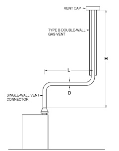
| For SI: 1 foot = 304.8 mm, 1 British thermal unit per hour = 0.2931 W. Table 504.2(2) is used when sizing a single-wall metal vent connector attached to a Type B double-wall gas vent. Note: The appliance may be either Category I draft hood equipped or fanassisted type. |
FIGURE B-2
TYPE B DOUBLE-WALL VENT SYSTEM SERVING A SINGLE
APPLIANCE WITH A SINGLE-WALL METAL VENT CONNECTOR
TABLE 504.2(2)
TYPE B DOUBLE-WALL GAS VENT
| Number of Appliances | Single |
| Appliance Type | Category I |
| Appliance Vent Connection | Single-wall metal connector |
| HEIGHT (H) (feet) |
LATERAL (L) (feet) |
VENT DIAMETER—(D) Inches | ||||||||||||||||||||||||||
| 3 | 4 | 5 | 6 | 7 | 8 | 9 | 10 | 12 | ||||||||||||||||||||
| APPLIANCE INPUT RATING IN THOUSANDS OF BTU/H | ||||||||||||||||||||||||||||
| FAN | NAT | FAN | NAT | FAN | NAT | FAN | NAT | FAN | NAT | FAN | NAT | FAN | NAT | FAN | NAT | FAN | NAT | |||||||||||
| Mln | Max | Max | Mln | Max | Max | Mln | Max | Max | Mln | Max | Max | Mln | Max | Max | Mln | Max | Max | Mln | Max | Max | Mln | Max | Max | Mln | Max | Max | ||
| 6 | 0 | 38 | 77 | 45 | 59 | 151 | 85 | 85 | 249 | 140 | 126 | 373 | 204 | 165 | 522 | 284 | 211 | 695 | 369 | 267 | 894 | 469 | 371 | 1,118 | 569 | 537 | 1.639 | 849 |
| 2 | 39 | 51 | 36 | 60 | 96 | 66 | 85 | 156 | 104 | 123 | 231 | 156 | 159 | 320 | 213 | 201 | 423 | 284 | 251 | 541 | 368 | 347 | 673 | 453 | 498 | 979 | 648 | |
| 4 | NA | NA | 33 | 74 | 92 | 63 | 102 | 152 | 102 | 146 | 225 | 152 | 187 | 313 | 208 | 237 | 416 | 277 | 295 | 533 | 360 | 409 | 664 | 443 | 584 | 971 | 638 | |
| 6 | NA | NA | 31 | 83 | 89 | 60 | 114 | 147 | 99 | 163 | 220 | 148 | 207 | 307 | 203 | 263 | 409 | 271 | 327 | 526 | 352 | 449 | 656 | 433 | 638 | 962 | 627 | |
| 8 | 0 | 37 | 83 | 50 | 58 | 164 | 93 | 83 | 273 | 154 | 123 | 412 | 234 | 161 | 580 | 319 | 206 | 777 | 414 | 258 | 1,002 | 536 | 360 | 1,257 | 658 | 521 | 1,852 | 967 |
| 2 | 39 | 56 | 39 | 59 | 108 | 75 | 83 | 176 | 119 | 121 | 261 | 179 | 155 | 363 | 246 | 197 | 482 | 321 | 246 | 617 | 417 | 339 | 768 | 513 | 486 | 1,120 | 743 | |
| 5 | NA | NA | 37 | 77 | 102 | 69 | 107 | 168 | 114 | 151 | 252 | 171 | 193 | 352 | 235 | 245 | 470 | 311 | 305 | 604 | 404 | 418 | 754 | 500 | 598 | 1,104 | 730 | |
| 8 | NA | NA | 33 | 90 | 95 | 64 | 122 | 161 | 107 | 175 | 243 | 163 | 223 | 342 | 225 | 280 | 458 | 300 | 344 | 591 | 392 | 470 | 740 | 486 | 665 | 1.089 | 715 | |
| 10 | 0 | 37 | 87 | 53 | 57 | 174 | 99 | 82 | 293 | 165 | 120 | 444 | 254 | 158 | 628 | 344 | 202 | 844 | 449 | 253 | 1,093 | 584 | 351 | 1,373 | 718 | 507 | 2,031 | 1,057 |
| 2 | 39 | 61 | 41 | 59 | 117 | 80 | 82 | 193 | 128 | 119 | 287 | 194 | 153 | 400 | 272 | 193 | 531 | 354 | 242 | 681 | 456 | 332 | 849 | 559 | 475 | 1,242 | 848 | |
| 5 | 52 | 56 | 39 | 76 | 111 | 76 | 105 | 185 | 122 | 148 | 277 | 186 | 190 | 388 | 261 | 241 | 518 | 344 | 299 | 667 | 443 | 409 | 834 | 544 | 584 | 1,224 | 825 | |
| 10 | NA | NA | 34 | 97 | 100 | 68 | 132 | 171 | 112 | 188 | 261 | 171 | 237 | 369 | 241 | 296 | 497 | 325 | 363 | 643 | 423 | 492 | 808 | 520 | 688 | 1,194 | 788 | |
| 15 | 0 | 36 | 93 | 57 | 56 | 190 | 111 | 80 | 325 | 186 | 116 | 499 | 283 | 153 | 713 | 388 | 195 | 966 | 523 | 244 | 1.259 | 681 | 336 | 1.591 | 838 | 488 | 2,374 | 1,237 |
| 2 | 38 | 69 | 47 | 57 | 136 | 93 | 80 | 225 | 149 | 115 | 337 | 224 | 148 | 473 | 314 | 187 | 631 | 413 | 232 | 812 | 543 | 319 | 1,015 | 673 | 457 | 1.491 | 983 | |
| 5 | 51 | 63 | 44 | 75 | 128 | 86 | 102 | 216 | 140 | 144 | 326 | 217 | 182 | 459 | 298 | 231 | 616 | 400 | 287 | 795 | 526 | 392 | 997 | 657 | 562 | 1,469 | 963 | |
| 10 | NA | NA | 39 | 95 | 116 | 79 | 128 | 201 | 131 | 182 | 308 | 203 | 228 | 438 | 284 | 284 | 592 | 381 | 349 | 768 | 501 | 470 | 966 | 628 | 664 | 1,433 | 928 | |
| 15 | NA | NA | NA | NA | NA | 72 | 158 | 186 | 124 | 220 | 290 | 192 | 272 | 418 | 269 | 334 | 568 | 367 | 404 | 742 | 484 | 540 | 937 | 601 | 750 | 1,399 | 894 | |
| 20 | 0 | 35 | 96 | 60 | 54 | 200 | 118 | 78 | 346 | 201 | 114 | 537 | 306 | 149 | 772 | 428 | 190 | 1,053 | 573 | 238 | 1,379 | 750 | 326 | 1,751 | 927 | 473 | 2,631 | 1,346 |
| 2 | 37 | 74 | 50 | 56 | 148 | 99 | 78 | 248 | 165 | 113 | 375 | 248 | 144 | 528 | 344 | 182 | 708 | 468 | 227 | 914 | 611 | 309 | 1,146 | 754 | 443 | 1.689 | 1.098 | |
| 5 | 50 | 68 | 47 | 73 | 140 | 94 | 100 | 239 | 158 | 141 | 363 | 239 | 178 | 514 | 334 | 224 | 692 | 457 | 279 | 896 | 596 | 381 | 1,126 | 734 | 547 | 1,665 | 1,074 | |
| 10 | NA | NA | 41 | 93 | 129 | 86 | 125 | 223 | 146 | 177 | 344 | 224 | 222 | 491 | 316 | 277 | 666 | 437 | 339 | 866 | 570 | 457 | 1,092 | 702 | 646 | 1,626 | 1,037 | |
| 15 | NA | NA | NA | NA | NA | 80 | 155 | 208 | 136 | 216 | 325 | 210 | 264 | 469 | 301 | 325 | 640 | 419 | 393 | 838 | 549 | 526 | 1,060 | 677 | 730 | 1,587 | 1,005 | |
| 20 | NA | NA | NA | NA | NA | NA | 186 | 192 | 126 | 254 | 306 | 196 | 309 | 448 | 285 | 374 | 616 | 400 | 448 | 810 | 526 | 592 | 1,028 | 651 | 808 | 1,550 | 973 | |
(continued)
TABLE 504.2(2)-continued
TYPE B DOUBLE-WALL GAS VENT
| Number of Appliances | Single |
| Appliance Type | Category I |
| Appliance Vent Connection | Single-wall metal connector |
| HEIGHT (H) (feet) |
LATERAL (L) (feet) |
VENT DIAMETER—(D) Inches | ||||||||||||||||||||||||||
| 3 | 4 | 5 | 6 | 7 | 8 | 9 | 10 | 12 | ||||||||||||||||||||
| APPLIANCE INPUT RATING IN THOUSANDS OF BTU/H | ||||||||||||||||||||||||||||
| FAN | NAT | FAN | NAT | FAN | NAT | FAN | NAT | FAN | NAT | FAN | NAT | FAN | NAT | FAN | NAT | FAN | NAT | |||||||||||
| Mln | Max | Max | Mln | Max | Max | Mln | Max | Max | Mln | Max | Max | Mln | Max | Max | Mln | Max | Max | Mln | Max | Max | Mln | Max | Max | Mln | Max | Max | ||
| 30 | 0 | 34 | 99 | 63 | 53 | 211 | 127 | 76 | 372 | 219 | 110 | 584 | 334 | 144 | 849 | 472 | 184 | 1,168 | 647 | 229 | 1,542 | 852 | 312 | 1.971 | 1,056 | 454 | 2,996 | 1,545 |
| 2 | 37 | 80 | 56 | 55 | 164 | 111 | 76 | 281 | 183 | 109 | 429 | 279 | 139 | 610 | 392 | 175 | 823 | 533 | 219 | 1,069 | 698 | 296 | 1,346 | 863 | 424 | 1,999 | 1,308 | |
| 5 | 49 | 74 | 52 | 72 | 157 | 106 | 98 | 271 | 173 | 136 | 417 | 271 | 171 | 595 | 382 | 215 | 806 | 521 | 269 | 1,049 | 684 | 366 | 1,324 | 846 | 524 | 1,971 | 1,283 | |
| 10 | NA | NA | NA | 91 | 144 | 98 | 122 | 255 | 168 | 171 | 397 | 257 | 213 | 570 | 367 | 265 | 777 | 501 | 327 | 1,017 | 662 | 440 | 1,287 | 821 | 620 | 1,927 | 1,234 | |
| 15 | NA | NA | NA | 115 | 131 | NA | 151 | 239 | 157 | 208 | 377 | 242 | 255 | 547 | 349 | 312 | 750 | 481 | 379 | 985 | 638 | 507 | 1,251 | 794 | 702 | 1,884 | 1,205 | |
| 20 | NA | NA | NA | NA | NA | NA | 181 | 223 | NA | 246 | 357 | 228 | 298 | 524 | 333 | 360 | 723 | 461 | 433 | 955 | 615 | 570 | 1,216 | 768 | 780 | 1,841 | 1,166 | |
| 30 | NA | NA | NA | NA | NA | NA | NA | NA | NA | NA | NA | NA | 389 | 477 | 305 | 461 | 670 | 426 | 541 | 895 | 574 | 704 | 1,147 | 720 | 937 | 1.759 | 1,101 | |
| 50 | 0 | 33 | 99 | 66 | 51 | 213 | 133 | 73 | 394 | 230 | 105 | 629 | 361 | 138 | 928 | 515 | 176 | 1,292 | 704 | 220 | 1,724 | 948 | 295 | 2,223 | 1,189 | 428 | 3,432 | 1,818 |
| 2 | 36 | 84 | 61 | 53 | 181 | 121 | 73 | 318 | 205 | 104 | 495 | 312 | 133 | 712 | 443 | 168 | 971 | 613 | 209 | 1,273 | 811 | 280 | 1,615 | 1,007 | 401 | 2,426 | 1,509 | |
| 5 | 48 | 80 | NA | 70 | 174 | 117 | 94 | 308 | 198 | 131 | 482 | 305 | 164 | 696 | 435 | 204 | 953 | 602 | 257 | 1,252 | 795 | 347 | 1,591 | 991 | 496 | 2,396 | 1,490 | |
| 10 | NA | NA | NA | 89 | 160 | NA | 118 | 292 | 186 | 162 | 461 | 292 | 203 | 671 | 420 | 253 | 923 | 583 | 313 | 1,217 | 765 | 418 | 1,551 | 963 | 589 | 2,347 | 1,455 | |
| 15 | NA | NA | NA | 112 | 148 | NA | 145 | 275 | 174 | 199 | 441 | 280 | 244 | 646 | 405 | 299 | 894 | 562 | 363 | 1,183 | 736 | 481 | 1,512 | 934 | 668 | 2,299 | 1,421 | |
| 20 | NA | NA | NA | NA | NA | NA | 176 | 257 | NA | 236 | 420 | 267 | 285 | 622 | 389 | 345 | 866 | 543 | 415 | 1,150 | 708 | 544 | 1,473 | 906 | 741 | 2,251 | 1,387 | |
| 30 | NA | NA | NA | NA | NA | NA | NA | NA | NA | 315 | 376 | NA | 373 | 573 | NA | 442 | 809 | 502 | 521 | 1,086 | 649 | 674 | 1,399 | 848 | 892 | 2,159 | 1,318 | |
| 100 | 0 | NA | NA | NA | 49 | 214 | NA | 69 | 403 | NA | 100 | 659 | 395 | 131 | 991 | 555 | 166 | 1,404 | 765 | 207 | 1,900 | 1,033 | 273 | 2,479 | 1,300 | 395 | 3,912 | 2,042 |
| 2 | NA | NA | NA | 51 | 192 | NA | 70 | 351 | NA | 98 | 563 | 373 | 125 | 828 | 508 | 158 | 1,152 | 698 | 196 | 1,532 | 933 | 259 | 1,970 | 1,168 | 371 | 3,021 | 1,817 | |
| 5 | NA | NA | NA | 67 | 186 | NA | 90 | 342 | NA | 125 | 551 | 366 | 156 | 813 | 501 | 194 | 1,134 | 688 | 240 | 1,511 | 921 | 322 | 1,945 | 1,153 | 460 | 2,990 | 1,796 | |
| 10 | NA | NA | NA | 85 | 175 | NA | 113 | 324 | NA | 153 | 532 | 354 | 191 | 789 | 486 | 238 | 1,104 | 672 | 293 | 1,477 | 902 | 389 | 1.905 | 1,133 | 547 | 2,938 | 1,763 | |
| 15 | NA | NA | NA | 132 | 162 | NA | 138 | 310 | NA | 188 | 511 | 343 | 230 | 764 | 473 | 281 | 1,075 | 656 | 342 | 1,443 | 884 | 447 | 1,865 | 1,110 | 618 | 2,888 | 1,730 | |
| 20 | NA | NA | NA | NA | NA | NA | 168 | 295 | NA | 224 | 487 | NA | 270 | 739 | 458 | 325 | 1,046 | 639 | 391 | 1,410 | 864 | 507 | 1,825 | 1,087 | 690 | 2,838 | 1,696 | |
| 30 | NA | NA | NA | NA | NA | NA | 231 | 264 | NA | 301 | 448 | NA | 355 | 685 | NA | 418 | 988 | NA | 491 | 1,343 | 824 | 631 | 1,747 | 1,041 | 834 | 2,739 | 1,627 | |
| 50 | NA | NA | NA | NA | NA | NA | NA | NA | NA | NA | NA | NA | 540 | 584 | NA | 617 | 866 | NA | 711 | 1,205 | NA | 895 | 1,591 | NA | 1,138 | 2,547 | 1,489 | |
| For SI: 1 inch = 25.4 mm, 1 foot = 304.8 mm, 1 British thermal unit per hour = 0.2931 W. |
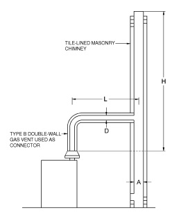
| Table 504.2(3) is used when sizing a Type B double-wall gas vent connector attached to a tile-lined masonry chimney. Note: “A” is the equivalent cross-sectional area of the tile liner. Note: The appliance may be either Category I draft hood equipped or fanassisted type. |
FIGURE B-3
VENT SYSTEM SERVING A SINGLE APPLIANCE
WITH A MASONRY CHIMNEY OF TYPE B
DOUBLE-WALL VENT CONNECTOR
TABLE 504.2(3)
MASONRY CHIMNEY
| Number of Appliances | Single |
| Appliance Type | Category I |
| Appliance Vent Connection | Type B double-wall connector |
| HEIGHT (H) (feet) |
LATERAL (L) (feet) |
TYPE B DOUBLE-WALL CONNECTOR DIAMETER-—(D) Inches to be used with chimney areas within the size limits at bottom | ||||||||||||||||||||||||||
| 3 | 4 | 5 | 6 | 7 | 8 | 9 | 10 | 12 | ||||||||||||||||||||
| APPLIANCE INPUT RATING IN THOUSANDS OF BTU/H | ||||||||||||||||||||||||||||
| FAN | NAT | FAN | NAT | FAN | NAT | FAN | NAT | FAN | NAT | FAN | NAT | FAN | NAT | FAN | NAT | FAN | NAT | |||||||||||
| Min | Max | Max | Min | Max | Max | Min | Max | Max | Min | Max | Max | Min | Max | Max | Min | Max | Max | Min | Max | Max | Min | Max | Max | Min | Max | Max | ||
| 6 | 2 | NA | NA | 28 | NA | NA | 52 | NA | NA | 86 | NA | NA | 130 | NA | NA | 180 | NA | NA | 247 | NA | NA | 320 | NA | NA | 401 | NA | NA | 581 |
| 5 | NA | NA | 25 | NA | NA | 49 | NA | NA | 82 | NA | NA | 117 | NA | NA | 165 | NA | NA | 231 | NA | NA | 298 | NA | NA | 376 | NA | NA | 561 | |
| 8 | 2 | NA | NA | 29 | NA | NA | 55 | NA | NA | 93 | NA | NA | 145 | NA | NA | 198 | NA | NA | 266 | 84 | 590 | 350 | 100 | 728 | 446 | 139 | 1,024 | 651 |
| 5 | NA | NA | 26 | NA | NA | 52 | NA | NA | 88 | NA | NA | 134 | NA | NA | 183 | NA | NA | 247 | NA | NA | 328 | 149 | 711 | 423 | 201 | 1,007 | 640 | |
| 8 | NA | NA | 24 | NA | NA | 48 | NA | NA | 83 | NA | NA | 127 | NA | NA | 175 | NA | NA | 239 | NA | NA | 318 | 173 | 695 | 410 | 231 | 990 | 623 | |
| 10 | 2 | NA | NA | 31 | NA | NA | 61 | NA | NA | 103 | NA | NA | 162 | NA | NA | 221 | 68 | 519 | 298 | 82 | 655 | 388 | 98 | 810 | 491 | 136 | 1,144 | 724 |
| 5 | NA | NA | 28 | NA | NA | 57 | NA | NA | 96 | NA | NA | 148 | NA | NA | 204 | NA | NA | 277 | 124 | 638 | 365 | 146 | 791 | 466 | 196 | 1,124 | 712 | |
| 10 | NA | NA | 25 | NA | NA | 50 | NA | NA | 87 | NA | NA | 139 | NA | NA | 191 | NA | NA | 263 | 155 | 610 | 347 | 182 | 762 | 444 | 240 | 1,093 | 668 | |
| 15 | 2 | NA | NA | 35 | NA | NA | 67 | NA | NA | 114 | NA | NA | 179 | 53 | 475 | 250 | 64 | 613 | 336 | 77 | 779 | 441 | 92 | 968 | 562 | 127 | 1,376 | 841 |
| 5 | NA | NA | 35 | NA | NA | 62 | NA | NA | 107 | NA | NA | 164 | NA | NA | 231 | 99 | 594 | 313 | 118 | 759 | 416 | 139 | 946 | 533 | 186 | 1,352 | 828 | |
| 10 | NA | NA | 28 | NA | NA | 55 | NA | NA | 97 | NA | NA | 153 | NA | NA | 216 | 126 | 565 | 296 | 148 | 727 | 394 | 173 | 912 | 567 | 229 | 1,315 | 777 | |
| 15 | NA | NA | NA | NA | NA | 48 | NA | NA | 89 | NA | NA | 141 | NA | NA | 201 | NA | NA | 281 | 171 | 698 | 375 | 198 | 880 | 485 | 259 | 1,280 | 742 | |
| 20 | 2 | NA | NA | 38 | NA | NA | 74 | NA | NA | 124 | NA | NA | 201 | 51 | 522 | 274 | 61 | 678 | 375 | 73 | 867 | 491 | 87 | 1,083 | 627 | 121 | 1,548 | 953 |
| 5 | NA | NA | 36 | NA | NA | 68 | NA | NA | 116 | NA | NA | 184 | 80 | 503 | 254 | 95 | 658 | 350 | 113 | 845 | 463 | 133 | 1,059 | 597 | 179 | 1,523 | 933 | |
| 10 | NA | NA | NA | NA | NA | 60 | NA | NA | 107 | NA | NA | 172 | NA | NA | 237 | 122 | 627 | 332 | 143 | 811 | 440 | 167 | 1,022 | 566 | 221 | 1,482 | 879 | |
| 15 | NA | NA | NA | NA | NA | NA | NA | NA | 97 | NA | NA | 159 | NA | NA | 220 | NA | NA | 314 | 165 | 780 | 418 | 191 | 987 | 541 | 251 | 1,443 | 840 | |
| 20 | NA | NA | NA | NA | NA | NA | NA | NA | 83 | NA | NA | 148 | NA | NA | 206 | NA | NA | 296 | 186 | 750 | 397 | 214 | 955 | 513 | 277 | 1,406 | 807 | |
(continued)
TABLE 504.2(3)—continued
MASONRY CHIMNEY
| Number of Appliances | Single |
| Appliance Type | Category I |
| Appliance Vent Connection | Type B double-wall connector |
| HEIGHT (H) (feet) |
LATERAL (L) (feet) |
TYPE B DOUBLE-WALL CONNECTOR DIAMETER —(D) Inches to be used with chimney areas within the size limits at bottom | ||||||||||||||||||||||||||
| 3 | 4 | 5 | 6 | 7 | 8 | 9 | 10 | 12 | ||||||||||||||||||||
| APPLIANCE INPUT RATING IN THOUSANDS OF BTU/H | ||||||||||||||||||||||||||||
| FAN | NAT | FAN | NAT | FAN | NAT | FAN | NAT | FAN | NAT | FAN | NAT | FAN | NAT | FAN | NAT | FAN | NAT | |||||||||||
| Min | Max | Max | Min | Max | Max | Min | Max | Max | Min | Max | Max | Min | Max | Max | Min | Max | Max | Min | Max | Max | Min | Max | Max | Min | Max | Max | ||
| 30 | 2 | NA | NA | 41 | NA | NA | 82 | NA | NA | 137 | NA | NA | 216 | 47 | 581 | 303 | 57 | 762 | 421 | 68 | 985 | 558 | 81 | 1,240 | 717 | 111 | 1,793 | 1,112 |
| 5 | NA | NA | NA | NA | NA | 76 | NA | NA | 128 | NA | NA | 198 | 75 | 561 | 281 | 90 | 741 | 393 | 106 | 962 | 526 | 125 | 1,216 | 683 | 169 | 1,766 | 1,094 | |
| 10 | NA | NA | NA | NA | NA | 67 | NA | NA | 115 | NA | NA | 184 | NA | NA | 263 | 115 | 709 | 373 | 135 | 927 | 500 | 158 | 1,176 | 648 | 210 | 1,721 | 1,025 | |
| 15 | NA | NA | NA | NA | NA | NA | NA | NA | 107 | NA | NA | 171 | NA | NA | 243 | NA | NA | 353 | 156 | 893 | 476 | 181 | 1,139 | 621 | 239 | 1,679 | 981 | |
| 20 | NA | NA | NA | NA | NA | NA | NA | NA | 91 | NA | NA | 159 | NA | NA | 227 | NA | NA | 332 | 176 | 860 | 450 | 203 | 1,103 | 592 | 264 | 1,638 | 940 | |
| 30 | NA | NA | NA | NA | NA | NA | NA | NA | NA | NA | NA | NA | NA | NA | 188 | NA | NA | 288 | NA | NA | 416 | 249 | 1,035 | 555 | 318 | 1,560 | 877 | |
| 50 | 2 | NA | NA | NA | NA | NA | 92 | NA | NA | 161 | NA | NA | 251 | NA | NA | 351 | 51 | 840 | 477 | 61 | 1,106 | 633 | 72 | 1,413 | 812 | 99 | 2,080 | 1,243 |
| 5 | NA | NA | NA | NA | NA | NA | NA | NA | 151 | NA | NA | 230 | NA | NA | 323 | 83 | 819 | 445 | 98 | 1,083 | 596 | 116 | 1,387 | 774 | 155 | 2,052 | 1,225 | |
| 10 | NA | NA | NA | NA | NA | NA | NA | NA | 138 | NA | NA | 215 | NA | NA | 304 | NA | NA | 424 | 126 | 1,047 | 567 | 147 | 1,347 | 733 | 195 | 2,006 | 1,147 | |
| 15 | NA | NA | NA | NA | NA | NA | NA | NA | 127 | NA | NA | 199 | NA | NA | 282 | NA | NA | 400 | 146 | 1,010 | 539 | 170 | 1,307 | 702 | 222 | 1,961 | 1,099 | |
| 20 | NA | NA | NA | NA | NA | NA | NA | NA | NA | NA | NA | 185 | NA | NA | 264 | NA | NA | 376 | 165 | 977 | 511 | 190 | 1,269 | 669 | 246 | 1,916 | 1,050 | |
| 30 | NA | NA | NA | NA | NA | NA | NA | NA | NA | NA | NA | NA | NA | NA | NA | NA | NA | 327 | NA | NA | 468 | 233 | 1,196 | 623 | 295 | 1,832 | 984 | |
| Minimum Internal Area of Chimney (square inches) |
12 | 19 | 28 | 38 | 50 | 63 | 78 | 95 | 132 | |||||||||||||||||||
| Maximum Internal Area of Chimney (square inches) |
Four times the listed appliance categorized vent area, flue collar area or draft hood outlet area. | |||||||||||||||||||||||||||
| For SI: 1 inch = 25.4 mm, 1 square inch = 645.16 mm2, 1 foot = 304.8 mm, 1 British thermal unit per hour = 0.2931 W. |
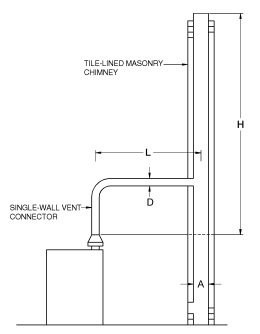
| Table 504.2(4) is used when sizing a single-wall vent connector attached to a tile-lined masonry chimney. Note: “A” is the equivalent cross-sectional area of the tile liner. Note: The appliance may be either Category I draft hood equipped or fanassisted type. |
FIGURE B-4
VENT SYSTEM SERVING A SINGLE APPLIANCE
USING A MASONRY CHIMNEY AND A
SINGLE-WALL METAL VENT CONNECTOR
TABLE 504.2(4)
MASONRY CHIMNEY
| Number of Appliances | Single |
| Appliance Type | Category I |
| Appliance Vent Connection | Single-wall metal connector |
| HEIGHT (H) (feet) |
LATERAL (L) (feet) |
SINGLE-WALL METAL CONNECTOR DIAMETER—(D) Inches to be used with chimney areas within the size limits at bottom | ||||||||||||||||||||||||||
| 3 | 4 | 5 | 6 | 7 | 8 | 9 | 10 | 12 | ||||||||||||||||||||
| APPLIANCE INPUT RATING IN THOUSANDS OF BTU/H | ||||||||||||||||||||||||||||
| FAN | NAT | FAN | NAT | FAN | NAT | FAN | NAT | FAN | NAT | FAN | NAT | FAN | NAT | FAN | NAT | FAN | NAT | |||||||||||
| Min | Max | Max | Min | Max | Max | Min | Max | Max | Min | Max | Max | Min | Max | Max | Min | Max | Max | Min | Max | Max | Min | Max | Max | Min | Max | Max | ||
| 6 | 2 | NA | NA | 28 | NA | NA | 52 | NA | NA | 86 | NA | NA | 130 | NA | NA | 180 | NA | NA | 247 | NA | NA | 319 | NA | NA | 400 | NA | NA | 580 |
| 5 | NA | NA | 25 | NA | NA | 48 | NA | NA | 81 | NA | NA | 116 | NA | NA | 164 | NA | NA | 230 | NA | NA | 297 | NA | NA | 375 | NA | NA | 560 | |
| 8 | 2 | NA | NA | 29 | NA | NA | 55 | NA | NA | 93 | NA | NA | 145 | NA | NA | 197 | NA | NA | 265 | NA | NA | 349 | 382 | 725 | 445 | 549 | 1,021 | 650 |
| 5 | NA | NA | 26 | NA | NA | 51 | NA | NA | 87 | NA | NA | 133 | NA | NA | 182 | NA | NA | 246 | NA | NA | 327 | NA | NA | 422 | 673 | 1,003 | 638 | |
| 8 | NA | NA | 23 | NA | NA | 47 | NA | NA | 82 | NA | NA | 126 | NA | NA | 174 | NA | NA | 237 | NA | NA | 317 | NA | NA | 408 | 747 | 985 | 621 | |
| 10 | 2 | NA | NA | 31 | NA | NA | 61 | NA | NA | 102 | NA | NA | 161 | NA | NA | 220 | 216 | 518 | 297 | 271 | 654 | 387 | 373 | 808 | 490 | 536 | 1,142 | 722 |
| 5 | NA | NA | 28 | NA | NA | 56 | NA | NA | 95 | NA | NA | 147 | NA | NA | 203 | NA | NA | 276 | 334 | 635 | 364 | 459 | 789 | 465 | 657 | 1,121 | 710 | |
| 10 | NA | NA | 24 | NA | NA | 49 | NA | NA | 86 | NA | NA | 137 | NA | NA | 189 | NA | NA | 261 | NA | NA | 345 | 547 | 758 | 441 | 771 | 1,088 | 665 | |
| 15 | 2 | NA | NA | 35 | NA | NA | 67 | NA | NA | 113 | NA | NA | 178 | 166 | 473 | 249 | 211 | 611 | 335 | 264 | 776 | 440 | 362 | 965 | 560 | 520 | 1,373 | 840 |
| 5 | NA | NA | 32 | NA | NA | 61 | NA | NA | 106 | NA | NA | 163 | NA | NA | 230 | 261 | 591 | 312 | 325 | 775 | 414 | 444 | 942 | 531 | 637 | 1,348 | 825 | |
| 10 | NA | NA | 27 | NA | NA | 54 | NA | NA | 96 | NA | NA | 151 | NA | NA | 214 | NA | NA | 294 | 392 | 722 | 392 | 531 | 907 | 504 | 749 | 1,309 | 774 | |
| 15 | NA | NA | NA | NA | NA | 46 | NA | NA | 87 | NA | NA | 138 | NA | NA | 198 | NA | NA | 278 | 452 | 692 | 372 | 606 | 873 | 481 | 841 | 1,272 | 738 | |
| 20 | 2 | NA | NA | 38 | NA | NA | 73 | NA | NA | 123 | NA | NA | 200 | 163 | 520 | 273 | 206 | 675 | 374 | 258 | 864 | 490 | 252 | 1,079 | 625 | 508 | 1,544 | 950 |
| 5 | NA | NA | 35 | NA | NA | 67 | NA | NA | 115 | NA | NA | 183 | 80 | NA | 252 | 255 | 655 | 348 | 317 | 842 | 461 | 433 | 1,055 | 594 | 623 | 1,518 | 930 | |
| 10 | NA | NA | NA | NA | NA | 59 | NA | NA | 105 | NA | NA | 170 | NA | NA | 235 | 312 | 622 | 330 | 382 | 806 | 437 | 517 | 1,016 | 562 | 733 | 1,475 | 875 | |
| 15 | NA | NA | NA | NA | NA | NA | NA | NA | 95 | NA | NA | 156 | NA | NA | 217 | NA | NA | 311 | 442 | 773 | 414 | 591 | 979 | 539 | 823 | 1,434 | 835 | |
| 20 | NA | NA | NA | NA | NA | NA | NA | NA | 80 | NA | NA | 144 | NA | NA | 202 | NA | NA | 292 | NA | NA | 392 | 663 | 944 | 510 | 911 | 1,394 | 800 | |
(continued)
TABLE 504.2(4)—continued
MASONRY CHIMNEY
| Number of Appliances | Single |
| Appliance Type | Category I |
| Appliance Vent Connection | Single-wall metal connector |
| HEIGHT (H) (feet) |
LATERAL (L) (feet) |
SINGLE-WALL METAL CONNECTOR DIAMETER—(D) Inches to be used with chimney areas within the size limits at bottom | ||||||||||||||||||||||||||
| 3 | 4 | 5 | 6 | 7 | 8 | 9 | 10 | 12 | ||||||||||||||||||||
| APPLIANCE INPUT RATING IN THOUSANDS OF BTU/H | ||||||||||||||||||||||||||||
| FAN | NAT | FAN | NAT | FAN | NAT | FAN | NAT | FAN | NAT | FAN | NAT | FAN | NAT | FAN | NAT | FAN | NAT | |||||||||||
| Min | Max | Max | Min | Max | Max | Min | Max | Max | Min | Max | Max | Min | Max | Max | Min | Max | Max | Min | Max | Max | Min | Max | Max | Min | Max | Max | ||
| 30 | 2 | NA | NA | 41 | NA | NA | 81 | NA | NA | 136 | NA | NA | 215 | 158 | 578 | 302 | 200 | 759 | 420 | 249 | 982 | 556 | 340 | 1,237 | 715 | 489 | 1,789 | 1,110 |
| 5 | NA | NA | NA | NA | NA | 75 | NA | NA | 127 | NA | NA | 196 | NA | NA | 279 | 245 | 737 | 391 | 306 | 958 | 524 | 417 | 1,210 | 680 | 600 | 1,760 | 1,090 | |
| 10 | NA | NA | NA | NA | NA | 66 | NA | NA | 113 | NA | NA | 182 | NA | NA | 260 | 300 | 703 | 370 | 370 | 920 | 496 | 500 | 1,168 | 644 | 708 | 1,713 | 1,020 | |
| 15 | NA | NA | NA | NA | NA | NA | NA | NA | 105 | NA | NA | 168 | NA | NA | 240 | NA | NA | 349 | 428 | 884 | 471 | 572 | 1,128 | 615 | 798 | 1,668 | 975 | |
| 20 | NA | NA | NA | NA | NA | NA | NA | NA | 88 | NA | NA | 155 | NA | NA | 223 | NA | NA | 327 | NA | NA | 445 | 643 | 1,089 | 585 | 883 | 1,624 | 932 | |
| 30 | NA | NA | NA | NA | NA | NA | NA | NA | NA | NA | NA | NA | NA | NA | 182 | NA | NA | 281 | NA | NA | 408 | NA | NA | 544 | 1,055 | 1,539 | 865 | |
| 50 | 2 | NA | NA | NA | NA | NA | 91 | NA | NA | 160 | NA | NA | 250 | NA | NA | 350 | 191 | 837 | 475 | 238 | 1,103 | 631 | 323 | 1,408 | 810 | 463 | 2,076 | 1,240 |
| 5 | NA | NA | NA | NA | NA | NA | NA | NA | 149 | NA | NA | 228 | NA | NA | 321 | NA | NA | 442 | 293 | 1,078 | 593 | 398 | 1,381 | 770 | 571 | 2,044 | 1,220 | |
| 10 | NA | NA | NA | NA | NA | NA | NA | NA | 136 | NA | NA | 212 | NA | NA | 301 | NA | NA | 420 | 355 | 1,038 | 562 | 447 | 1,337 | 728 | 674 | 1,994 | 1,140 | |
| 15 | NA | NA | NA | NA | NA | NA | NA | NA | 124 | NA | NA | 195 | NA | NA | 278 | NA | NA | 395 | NA | NA | 533 | 546 | 1,294 | 695 | 761 | 1,945 | 1,090 | |
| 20 | NA | NA | NA | NA | NA | NA | NA | NA | NA | NA | NA | 180 | NA | NA | 258 | NA | NA | 370 | NA | NA | 504 | 616 | 1,251 | 660 | 844 | 1,898 | 1,040 | |
| 30 | NA | NA | NA | NA | NA | 48 | NA | NA | NA | NA | NA | NA | NA | NA | NA | NA | NA | 318 | NA | NA | 458 | NA | NA | 610 | 1,009 | 1,805 | 970 | |
| Minimum Internal Area of Chimney (square inches) |
12 | 19 | 28 | 38 | 50 | 63 | 78 | 95 | 132 | |||||||||||||||||||
| Maximum Internal Area of Chimney (square inches) |
Four times the listed appliance categorized vent area, flue collar area or draft hood outlet area. | |||||||||||||||||||||||||||
| For SI: 1 inch = 25.4 mm, 1 square inch = 645.16 mm2, 1 foot = 304.8 mm, 1 British thermal unit per hour = 0.2931 W. |
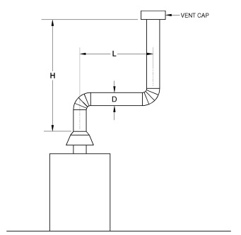
| Asbestos cement Type B or single-wall metal vent serving a single drafthood-equipped appliance [see Table 504.2(5)]. |
FIGURE B-5
ASBESTOS CEMENT TYPE B OR SINGLE-WALL
METAL VENT SYSTEM SERVING A SINGLE
DRAFT-HOOD-EQUIPPED APPLIANCE
TABLE 504.2(5)
SINGLE-WALL METAL PIPE OR TYPE B ASBESTOS CEMENT VENT
| Number of Appliances | Single |
| Appliance Type | Draft hood equipped |
| Appliance Vent Connection | Connected directly to pipe or vent |
| HEIGHT (H) (feet) |
LATERAL (L) (feet) |
VENT DIAMETER—(D) inches | |||||||
| 3 | 4 | 5 | 6 | 7 | 8 | 10 | 12 | ||
| MAXIMUM APPLIANCE INPUT RATING IN THOUSANDS OF BTU/H | |||||||||
| 6 | 0 | 39 | 70 | 116 | 170 | 232 | 312 | 500 | 750 |
| 2 | 31 | 55 | 94 | 141 | 194 | 260 | 415 | 620 | |
| 5 | 28 | 51 | 88 | 128 | 177 | 242 | 390 | 600 | |
| 8 | 0 | 42 | 76 | 126 | 185 | 252 | 340 | 542 | 815 |
| 2 | 32 | 61 | 102 | 154 | 210 | 284 | 451 | 680 | |
| 5 | 29 | 56 | 95 | 141 | 194 | 264 | 430 | 648 | |
| 10 | 24 | 49 | 86 | 131 | 180 | 250 | 406 | 625 | |
| 10 | 0 | 45 | 84 | 138 | 202 | 279 | 372 | 606 | 912 |
| 2 | 35 | 67 | 111 | 168 | 233 | 311 | 505 | 760 | |
| 5 | 32 | 61 | 104 | 153 | 215 | 289 | 480 | 724 | |
| 10 | 27 | 54 | 94 | 143 | 200 | 274 | 455 | 700 | |
| 15 | NA | 46 | 84 | 130 | 186 | 258 | 432 | 666 | |
| 15 | 0 | 49 | 91 | 151 | 223 | 312 | 420 | 684 | 1,040 |
| 2 | 39 | 72 | 122 | 186 | 260 | 350 | 570 | 865 | |
| 5 | 35 | 67 | 110 | 170 | 240 | 325 | 540 | 825 | |
| 10 | 30 | 58 | 103 | 158 | 223 | 308 | 514 | 795 | |
| 15 | NA | 50 | 93 | 144 | 207 | 291 | 488 | 760 | |
| 20 | NA | NA | 82 | 132 | 195 | 273 | 466 | 726 | |
| 20 | 0 | 53 | 101 | 163 | 252 | 342 | 470 | 770 | 1,190 |
| 2 | 42 | 80 | 136 | 210 | 286 | 392 | 641 | 990 | |
| 5 | 38 | 74 | 123 | 192 | 264 | 364 | 610 | 945 | |
| 10 | 32 | 65 | 115 | 178 | 246 | 345 | 571 | 910 | |
| 15 | NA | 55 | 104 | 163 | 228 | 326 | 550 | 870 | |
| 20 | NA | NA | 91 | 149 | 214 | 306 | 525 | 832 | |
| 30 | 0 | 56 | 108 | 183 | 276 | 384 | 529 | 878 | 1,370 |
| 2 | 44 | 84 | 148 | 230 | 320 | 441 | 730 | 1,140 | |
| 5 | NA | 78 | 137 | 210 | 296 | 410 | 694 | 1,080 | |
| 10 | NA | 68 | 125 | 196 | 274 | 388 | 656 | 1,050 | |
| 15 | NA | NA | 113 | 177 | 258 | 366 | 625 | 1,000 | |
| 20 | NA | NA | 99 | 163 | 240 | 344 | 596 | 960 | |
| 30 | NA | NA | NA | NA | 192 | 295 | 540 | 890 | |
| 50 | 0 | NA | 120 | 210 | 310 | 443 | 590 | 980 | 1,550 |
| 2 | NA | 95 | 171 | 260 | 370 | 492 | 820 | 1,290 | |
| 5 | NA | NA | 159 | 234 | 342 | 474 | 780 | 1,230 | |
| 10 | NA | NA | 146 | 221 | 318 | 456 | 730 | 1,190 | |
| 15 | NA | NA | NA | 200 | 292 | 407 | 705 | 1,130 | |
| 20 | NA | NA | NA | 185 | 276 | 384 | 670 | 1,080 | |
| 30 | NA | NA | NA | NA | 222 | 330 | 605 | 1,010 | |
| For SI: 1 inch = 25.4 mm, 1 foot = 304.8 mm, 1 British thermal unit per hour = 0.2931 W. |
TABLE 504.2(6)
EXTERIOR MASONRY CHIMNEY
| Number of Appliances | Single |
| Appliance Type | NAT |
| Appliance Vent Connection | Type B double-wall connector |
| MINIMUM ALLOWABLE INPUT RATING OF SPACE-HEATING APPLIANCE IN THOUSANDS OF BTU PER HOUR | |||||||||
| VENT HEIGHT (feet) |
Internal area of chimney (square inches) | ||||||||
| 12 | 19 | 28 | 38 | 50 | 63 | 78 | 113 | ||
| 37°F or Greater | Local 99% Winter Design Temperature: 37°F or Greater | ||||||||
| 6 | 0 | 0 | 0 | 0 | 0 | 0 | 0 | 0 | |
| 8 | 0 | 0 | 0 | 0 | 0 | 0 | 0 | 0 | |
| 10 | 0 | 0 | 0 | 0 | 0 | 0 | 0 | 0 | |
| 15 | NA | 0 | 0 | 0 | 0 | 0 | 0 | 0 | |
| 20 | NA | NA | 123 | 190 | 249 | 184 | 0 | 0 | |
| 30 | NA | NA | NA | NA | NA | 393 | 334 | 0 | |
| 50 | NA | NA | NA | NA | NA | NA | NA | 579 | |
| 27 to 36°F | Local 99% Winter Design Temperature: 27 to 36°F | ||||||||
| 6 | 0 | 0 | 68 | 116 | 156 | 180 | 212 | 266 | |
| 8 | 0 | 0 | 82 | 127 | 167 | 187 | 214 | 263 | |
| 10 | 0 | 51 | 97 | 141 | 183 | 201 | 225 | 265 | |
| 15 | NA | NA | NA | NA | 233 | 253 | 274 | 305 | |
| 20 | NA | NA | NA | NA | NA | 307 | 330 | 362 | |
| 30 | NA | NA | NA | NA | NA | 419 | 445 | 485 | |
| 50 | NA | NA | NA | NA | NA | NA | NA | 763 | |
| 17 to 26°F | Local 99% Winter Design Temperature: 17 to 26°F | ||||||||
| 6 | NA | NA | NA | NA | NA | 215 | 259 | 349 | |
| 8 | NA | NA | NA | NA | 197 | 226 | 264 | 352 | |
| 10 | NA | NA | NA | NA | 214 | 245 | 278 | 358 | |
| 15 | NA | NA | NA | NA | NA | 296 | 331 | 398 | |
| 20 | NA | NA | NA | NA | NA | 352 | 387 | 457 | |
| 30 | NA | NA | NA | NA | NA | NA | 507 | 581 | |
| 50 | NA | NA | NA | NA | NA | NA | NA | NA | |
| 5 to 16°F | Local 99% Winter Design Temperature: 5 to 16°F | ||||||||
| 6 | NA | NA | NA | NA | NA | NA | NA | 416 | |
| 8 | NA | NA | NA | NA | NA | NA | 312 | 423 | |
| 10 | NA | NA | NA | NA | NA | 289 | 331 | 430 | |
| 15 | NA | NA | NA | NA | NA | NA | 393 | 485 | |
| 20 | NA | NA | NA | NA | NA | NA | 450 | 547 | |
| 30 | NA | NA | NA | NA | NA | NA | NA | 682 | |
| 50 | NA | NA | NA | NA | NA | NA | NA | 972 | |
| -10 to 4°F | Local 99% Winter Design Temperature: -10 to 4°F | ||||||||
| 6 | NA | NA | NA | NA | NA | NA | NA | 484 | |
| 8 | NA | NA | NA | NA | NA | NA | NA | 494 | |
| 10 | NA | NA | NA | NA | NA | NA | NA | 513 | |
| 15 | NA | NA | NA | NA | NA | NA | NA | 586 | |
| 20 | NA | NA | NA | NA | NA | NA | NA | 650 | |
| 30 | NA | NA | NA | NA | NA | NA | NA | 805 | |
| 50 | NA | NA | NA | NA | NA | NA | NA | 1,003 | |
| -11°F or Lower | Local 99% Winter Design Temperature: -11°F or Lower | ||||||||
| Not recommended for any vent configurations | |||||||||
| For SI: °C = (°F – 32)/1.8, 1 inch = 25.4 mm, 1 foot = 304.8 mm, 1 British thermal unit per hour = 0.2931 W. |
| Note: See Figure B-19 in Appendix B for a map showing local 99 percent winter design temperatures in the United States. |
504.2.1 Vent obstructions.
These venting tables shall not be used where obstructions, as described in Section 503.15, are installed in the venting system. The installation of vents serving listed appliances with vent dampers shall be in accordance with the appliance manufacturer’s instructions or in accordance with the following:
1. The maximum capacity of the vent system shall be determined using the “NAT Max” column.
2. The minimum capacity shall be determined as if the appliance were a fan-assisted appliance, using the “FAN Min” column to determine the minimum capacity of the vent system. Where the corresponding “FAN Min” is “NA,” the vent configuration shall not be permitted and an alternative venting configuration shall be utilized.
504.2.2 Minimum size.
Where the vent size determined from the tables is smaller than the appliance draft hood outlet or flue collar, the smaller size shall be permitted to be used provided that all of the following requirements are met:
1. The total vent height (H) is at least 10 feet (3048 mm).
2. Vents for appliance draft hood outlets or flue collars 12 inches (305 mm) in diameter or smaller are not reduced more than one table size.
3. Vents for appliance draft hood outlets or flue collars larger than 12 inches (305 mm) in diameter are not reduced more than two table sizes.
4. The maximum capacity listed in the tables for a fan-assisted appliance is reduced by 10 percent (0.90 × maximum table capacity).
5. The draft hood outlet is greater than 4 inches (102 mm) in diameter. Do not connect a 3-inch-diameter (76 mm) vent to a 4-inch-diameter (102 mm) draft hood outlet. This provision shall not apply to fan-assisted appliances.
504.2.3 Vent offsets.
Single-appliance venting configurations with zero (0) lateral lengths in Tables 504.2(1), 504.2(2) and 504.2(5) shall not have elbows in the venting system. Single-appliance venting configurations with lateral lengths include two 90-degree (1.57 rad) elbows. For each additional elbow up to and including 45 degrees (0.79 rad), the maximum capacity listed in the venting tables shall be reduced by 5 percent. For each additional elbow greater than 45 degrees (0.79 rad) up to and including 90 degrees (1.57 rad), the maximum capacity listed in the venting tables shall be reduced by 10 percent. Where multiple offsets occur in a vent, the total lateral length of all offsets combined shall not exceed that specified in Tables 504.2(1) through 504.2(5).
504.2.4 Zero lateral.
Zero (0) lateral (L) shall apply only to a straight vertical vent attached to a top outlet draft hood or flue collar.
504.2.5 High-altitude installations.
Sea-level input ratings shall be used when determining maximum capacity for high altitude installation. Actual input (derated for altitude) shall be used for determining minimum capacity for high altitude installation.
504.2.6 Multiple input rate appliances.
For appliances with more than one input rate, the minimum vent capacity (FAN Min) determined from the tables shall be less than the lowest appliance input rating, and the maximum vent capacity (FAN Max/NAT Max) determined from the tables shall be greater than the highest appliance rating input.
504.2.7 Liner system sizing.
Listed corrugated metallic chimney liner systems in masonry chimneys shall be sized by using IFGC Table 504.2(1) or 504.2(2) for Type B vents with the maximum capacity reduced by 20 percent (0.80 × maximum capacity) and the minimum capacity as shown in IFGC Table 504.2(1) or 504.2(2). Corrugated metallic liner systems installed with bends or offsets shall have their maximum capacity further reduced in accordance with IFGC Section 504.2.3. Approved metallic liners, other than listed corrugated metallic liner systems, installed in accordance with amended IFGC Section 501.12, shall be sized by using IFGC Table 504.2(1) or 504.2(2) for Type B vents.
When IFGC Table 504.2(1) or 504.2(2) permits more than one diameter for a connector or vent of a fan-assisted appliance, the smallest permitted diameter shall be used.
504.2.8 Vent area and diameter.
Where the vertical vent has a larger diameter than the vent connector, the vertical vent diameter shall be used to determine the minimum vent capacity, and the connector diameter shall be used to determine the maximum vent capacity. The flow area of the vertical vent shall not exceed four times the flow area of the listed appliance categorized vent area, flue collar area, or draft hood outlet area unless designated in accordance with approved engineering methods.
504.2.9 Chimney and vent locations.
Tables 504.2(1), 504.2(2), 504.2(3), 504.2(4) and 504.2(5) shall be used only for chimneys and vents not exposed to the outdoors below the roof line. A Type B vent or listed chimney lining system passing through an unused masonry chimney flue shall not be considered to be exposed to the outdoors. Where vents extend outdoors above the roof more than 5 feet (1524 mm) higher than required by Figure 503.6.4, and where vents terminate in accordance with Section 503.6.4, Item 2, the outdoor portion of the vent shall be enclosed as required by this section for vents not considered to be exposed to the outdoors or such venting system shall be engineered. A Type B vent shall not be considered to be exposed to the outdoors where it passes through an unventilated enclosure or chase insulated to a value of not less than R8.
Table 504.2(3) in combination with Table 504.2(6) shall be used for clay-tile-lined exterior masonry chimneys, provided that all of the following are met:
1. Vent connector is a Type B double wall.
2. Vent connector length is limited to 11/2 feet for each inch (18 mm per mm) of vent connector diameter.
3. The appliance is draft hood equipped.
4. The input rating is less than the maximum capacity given by Table 504.2(3).
5. For a water heater, the outdoor design temperature is not less than 5°F (-15°C).
6. For a space-heating appliance, the input rating is greater than the minimum capacity given by Table 504.2(6).
504.2.10 Corrugated vent connector size.
Corrugated vent connectors shall be not smaller than the listed appliance categorized vent diameter, flue collar diameter or draft hood outlet diameter.
504.2.11 Vent connector size limitation.
Vent connectors shall not be increased in size more than two sizes greater than the listed appliance categorized vent diameter, flue collar diameter or draft hood outlet diameter.
504.2.12 Component commingling.
In a single run of vent or vent connector, different diameters and types of vent and connector components shall be permitted to be used, provided that all such sizes and types are permitted by the tables.
504.2.13 Draft hood conversion accessories.
Draft hood conversion accessories for use with masonry chimneys venting listed Category I fan-assisted appliances shall be listed and installed in accordance with the manufacturer’s installation instructions for such listed accessories.
504.2.14 Table interpolation.
Interpolation shall be permitted in calculating capacities for vent dimensions that fall between the table entries.
504.2.15 Extrapolation prohibited.
Extrapolation beyond the table entries shall not be permitted.
504.2.16 Engineering calculations.
For vent heights less than 6 feet (1829 mm) and greater than shown in the tables, engineering methods shall be used to calculate vent capacities.
504.2.17 Height entries.
Where the actual height of a vent falls between entries in the height column of the applicable table in Tables 504.2(1) through 504.2(6), either interpolation shall be used or the lower appliance input rating shown in the table entries shall be used for FAN MAX and NAT MAX column values and the higher appliance input rating shall be used for the FAN MIN column values.
504.3 Application of multiple appliance vent Tables 504.3(1) through 504.3(7).
The application of Tables 504.3(1) through 504.3(7) shall be subject to the requirements of Sections 504.3.1 through 504.3.28.
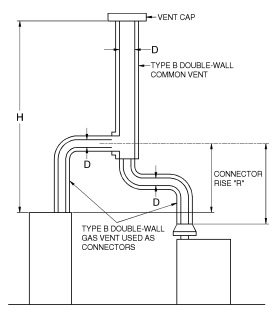
| Table 504.3(1) is used when sizing Type B double-wall vent connectors attached to a Type B double-wall common vent. Note: Each appliance may be either Category I draft hood equipped or fanassisted type. |
FIGURE B-6
VENT SYSTEM SERVING TWO OR MORE APPLIANCES
WITH TYPE B DOUBLE-WALL VENT AND TYPE B
DOUBLE-WALL VENT CONNECTOR
TABLE 504.3(1)
TYPE B DOUBLE-WALL VENT
| Number of Appliances | Two or more |
| Appliance Type | Category I |
| Appliance Vent Connection | Type B double-wall connector |
| VENT CONNECTOR CAPACITY | |||||||||||||||||||||||||
| VENT HEIGHT (H) (feet) |
CONNECTOR RISE (R) (feet) |
TYPE B DOUBLE-WALL VENT AND CONNECTOR DIAMETER—(D) inches | |||||||||||||||||||||||
| 3 | 4 | 5 | 6 | 7 | 8 | 9 | 10 | ||||||||||||||||||
| APPLIANCE INPUT RATING LIMITS IN THOUSANDS OF BTU/H | |||||||||||||||||||||||||
| FAN | NAT | FAN | NAT | FAN | NAT | FAN | NAT | FAN | NAT | FAN | NAT | FAN | NAT | FAN | NAT | ||||||||||
| Min | Max | Max | Min | Max | Max | Min | Max | Max | Min | Max | Max | Min | Max | Max | Min | Max | Max | Min | Max | Max | Min | Max | Max | ||
| 6 | 1 | 22 | 37 | 26 | 35 | 66 | 46 | 46 | 106 | 72 | 58 | 164 | 104 | 77 | 225 | 142 | 92 | 296 | 185 | 109 | 376 | 237 | 128 | 466 | 289 |
| 2 | 23 | 41 | 31 | 37 | 75 | 55 | 48 | 121 | 86 | 60 | 183 | 124 | 79 | 253 | 168 | 95 | 333 | 220 | 112 | 424 | 282 | 131 | 526 | 345 | |
| 3 | 24 | 44 | 35 | 38 | 81 | 62 | 49 | 132 | 96 | 62 | 199 | 139 | 82 | 275 | 189 | 97 | 363 | 248 | 114 | 463 | 317 | 134 | 575 | 386 | |
| 8 | 1 | 22 | 40 | 27 | 35 | 72 | 48 | 49 | 114 | 76 | 64 | 176 | 109 | 84 | 243 | 148 | 100 | 320 | 194 | 118 | 408 | 248 | 138 | 507 | 303 |
| 2 | 23 | 44 | 32 | 36 | 80 | 57 | 51 | 128 | 90 | 66 | 195 | 129 | 86 | 269 | 175 | 103 | 356 | 230 | 121 | 454 | 294 | 141 | 564 | 358 | |
| 3 | 24 | 47 | 36 | 37 | 87 | 64 | 53 | 139 | 101 | 67 | 210 | 145 | 88 | 290 | 198 | 105 | 384 | 258 | 123 | 492 | 330 | 143 | 612 | 402 | |
| 10 | 1 | 22 | 43 | 28 | 34 | 78 | 50 | 49 | 123 | 78 | 65 | 189 | 113 | 89 | 257 | 154 | 106 | 341 | 200 | 125 | 436 | 257 | 146 | 542 | 314 |
| 2 | 23 | 47 | 33 | 36 | 86 | 59 | 51 | 136 | 93 | 67 | 206 | 134 | 91 | 282 | 182 | 109 | 374 | 238 | 128 | 479 | 305 | 149 | 596 | 372 | |
| 3 | 24 | 50 | 37 | 37 | 92 | 67 | 52 | 146 | 104 | 69 | 220 | 150 | 94 | 303 | 205 | 111 | 402 | 268 | 131 | 515 | 342 | 152 | 642 | 417 | |
| 15 | 1 | 21 | 50 | 30 | 33 | 89 | 53 | 47 | 142 | 83 | 64 | 220 | 120 | 88 | 298 | 163 | 110 | 389 | 214 | 134 | 493 | 273 | 162 | 609 | 333 |
| 2 | 22 | 53 | 35 | 35 | 96 | 63 | 49 | 153 | 99 | 66 | 235 | 142 | 91 | 320 | 193 | 112 | 419 | 253 | 137 | 532 | 323 | 165 | 658 | 394 | |
| 3 | 24 | 55 | 40 | 36 | 102 | 71 | 51 | 163 | 111 | 68 | 248 | 160 | 93 | 339 | 218 | 115 | 445 | 286 | 140 | 565 | 365 | 167 | 700 | 444 | |
| 20 | 1 | 21 | 54 | 31 | 33 | 99 | 56 | 46 | 157 | 87 | 62 | 246 | 125 | 86 | 334 | 171 | 107 | 436 | 224 | 131 | 552 | 285 | 158 | 681 | 347 |
| 2 | 22 | 57 | 37 | 34 | 105 | 66 | 48 | 167 | 104 | 64 | 259 | 149 | 89 | 354 | 202 | 110 | 463 | 265 | 134 | 587 | 339 | 161 | 725 | 414 | |
| 3 | 23 | 60 | 42 | 35 | 110 | 74 | 50 | 176 | 116 | 66 | 271 | 168 | 91 | 371 | 228 | 113 | 486 | 300 | 137 | 618 | 383 | 164 | 764 | 466 | |
| 30 | 1 | 20 | 62 | 33 | 31 | 113 | 59 | 45 | 181 | 93 | 60 | 288 | 134 | 83 | 391 | 182 | 103 | 512 | 238 | 125 | 649 | 305 | 151 | 802 | 372 |
| 2 | 21 | 64 | 39 | 33 | 118 | 70 | 47 | 190 | 110 | 62 | 299 | 158 | 85 | 408 | 215 | 105 | 535 | 282 | 129 | 679 | 360 | 155 | 840 | 439 | |
| 3 | 22 | 66 | 44 | 34 | 123 | 79 | 48 | 198 | 124 | 64 | 309 | 178 | 88 | 423 | 242 | 108 | 555 | 317 | 132 | 706 | 405 | 158 | 874 | 494 | |
| 50 | 1 | 19 | 71 | 36 | 30 | 133 | 64 | 43 | 216 | 101 | 57 | 349 | 145 | 78 | 477 | 197 | 97 | 627 | 257 | 120 | 797 | 330 | 144 | 984 | 403 |
| 2 | 21 | 73 | 43 | 32 | 137 | 76 | 45 | 223 | 119 | 59 | 358 | 172 | 81 | 490 | 234 | 100 | 645 | 306 | 123 | 820 | 392 | 148 | 1,014 | 478 | |
| 3 | 22 | 75 | 48 | 33 | 141 | 86 | 46 | 229 | 134 | 61 | 366 | 194 | 83 | 502 | 263 | 103 | 661 | 343 | 126 | 842 | 441 | 151 | 1,043 | 538 | |
| 100 | 1 | 18 | 82 | 37 | 28 | 158 | 66 | 40 | 262 | 104 | 53 | 442 | 150 | 73 | 611 | 204 | 91 | 810 | 266 | 112 | 1,038 | 341 | 135 | 1,285 | 417 |
| 2 | 19 | 83 | 44 | 30 | 161 | 79 | 42 | 267 | 123 | 55 | 447 | 178 | 75 | 619 | 242 | 94 | 822 | 316 | 115 | 1,054 | 405 | 139 | 1,306 | 494 | |
| 3 | 20 | 84 | 50 | 31 | 163 | 89 | 44 | 272 | 138 | 57 | 452 | 109 | 78 | 627 | 272 | 97 | 834 | 355 | 118 | 1,069 | 455 | 142 | 1,327 | 555 | |
| COMMON VENT CAPACITY | |||||||||||||||||||||
| VENT HEIGHT (H) (feet) |
|||||||||||||||||||||
| 4 | 5 | 6 | 7 | 8 | 9 | 10 | |||||||||||||||
| COMBINED APPLIANCE INPUT RATING IN THOUSANDS OF BTU/H | |||||||||||||||||||||
| FAN +FAN | FAN +NAT | NAT +NAT | FAN +FAN | FAN +NAT | NAT +NAT | FAN +FAN | FAN +NAT | NAT +NAT | FAN +FAN | FAN +NAT | NAT +NAT | FAN +FAN | FAN +NAT | NAT +NAT | FAN +FAN | FAN +NAT | NAT +NAT | FAN +FAN | FAN +NAT | NAT +NAT | |
| 6 | 92 | 81 | 65 | 140 | 116 | 103 | 204 | 161 | 147 | 309 | 248 | 200 | 404 | 314 | 260 | 547 | 434 | 335 | 672 | 520 | 410 |
| 8 | 101 | 90 | 73 | 155 | 129 | 114 | 224 | 178 | 163 | 339 | 275 | 223 | 444 | 348 | 290 | 602 | 480 | 378 | 740 | 577 | 465 |
| 10 | 110 | 97 | 79 | 169 | 141 | 124 | 243 | 194 | 178 | 367 | 299 | 242 | 477 | 377 | 315 | 649 | 522 | 405 | 800 | 627 | 495 |
| 15 | 125 | 112 | 91 | 195 | 164 | 144 | 283 | 228 | 206 | 427 | 352 | 280 | 556 | 444 | 365 | 753 | 612 | 465 | 924 | 733 | 565 |
| 20 | 136 | 123 | 102 | 215 | 183 | 160 | 314 | 255 | 229 | 475 | 394 | 310 | 621 | 499 | 405 | 842 | 688 | 523 | 1,035 | 826 | 640 |
| 30 | 152 | 138 | 118 | 244 | 210 | 185 | 361 | 297 | 266 | 547 | 459 | 360 | 720 | 585 | 470 | 979 | 808 | 605 | 1,209 | 975 | 740 |
| 50 | 167 | 153 | 134 | 279 | 244 | 214 | 421 | 353 | 310 | 641 | 547 | 423 | 854 | 706 | 550 | 1,164 | 977 | 705 | 1,451 | 1,188 | 860 |
| 100 | 175 | 163 | NA | 311 | 277 | NA | 489 | 421 | NA | 751 | 658 | 479 | 1,025 | 873 | 625 | 1,408 | 1,215 | 800 | 1,784 | 1,502 | 975 |
(continued)
TABLE 504.3(1)-continued
TYPE B DOUBLE-WALL VENT
| Number of Appliances | Two or more |
| Appliance Type | Category I |
| Appliance Vent Connection | Type B double-wall connector |
| VENT CONNECTOR CAPACITY | ||||||||||||||||||||||
| VENT HEIGHT (H) (feet) |
CONNECTOR RISE (R) (feet) |
TYPE B DOUBLE-WALL VENT AND DIAMETER—(D) inches | ||||||||||||||||||||
| 12 | 14 | 16 | 18 | 20 | 22 | 24 | ||||||||||||||||
| APPLIANCE INPUT RATING LIMITS IN THOUSANDS OF BTU/H | ||||||||||||||||||||||
| FAN | NAT | FAN | NAT | FAN | NAT | FAN | NAT | FAN | NAT | FAN | NAT | FAN | NAT | |||||||||
| Min | Max | Max | Min | Max | Max | Min | Max | Max | Min | Max | Max | Min | Max | Max | Min | Max | Max | Min | Max | Max | ||
| 6 | 2 | 174 | 764 | 496 | 223 | 1,046 | 653 | 281 | 1,371 | 853 | 346 | 1,772 | 1,080 | NA | NA | NA | NA | NA | NA | NA | NA | NA |
| 4 | 180 | 897 | 616 | 230 | 1,231 | 827 | 287 | 1,617 | 1,081 | 352 | 2,069 | 1,370 | NA | NA | NA | NA | NA | NA | NA | NA | NA | |
| 6 | NA | NA | NA | NA | NA | NA | NA | NA | NA | NA | NA | NA | NA | NA | NA | NA | NA | NA | NA | NA | NA | |
| 8 | 2 | 186 | 822 | 516 | 238 | 1,126 | 696 | 298 | 1,478 | 910 | 365 | 1,920 | 1,150 | NA | NA | NA | NA | NA | NA | NA | NA | NA |
| 4 | 192 | 952 | 644 | 244 | 1,307 | 884 | 305 | 1,719 | 1,150 | 372 | 2,211 | 1,460 | 471 | 2,737 | 1,800 | 560 | 3,319 | 2,180 | 662 | 3,957 | 2,590 | |
| 6 | 198 | 1,050 | 772 | 252 | 1,445 | 1,072 | 313 | 1,902 | 1,390 | 380 | 2,434 | 1,770 | 478 | 3,018 | 2,180 | 568 | 3,665 | 2,640 | 669 | 4,373 | 3,130 | |
| 10 | 2 | 196 | 870 | 536 | 249 | 1,195 | 730 | 311 | 1,570 | 955 | 379 | 2,049 | 1,205 | NA | NA | NA | NA | NA | NA | NA | NA | NA |
| 4 | 201 | 997 | 664 | 256 | 1,371 | 924 | 318 | 1,804 | 1,205 | 387 | 2,332 | 1,535 | 486 | 2,887 | 1,890 | 581 | 3,502 | 2,280 | 686 | 4,175 | 2,710 | |
| 6 | 207 | 1,095 | 792 | 263 | 1,509 | 1,118 | 325 | 1,989 | 1,455 | 395 | 2,556 | 1,865 | 494 | 3,169 | 2,290 | 589 | 3,849 | 2,760 | 694 | 4,593 | 3,270 | |
| 15 | 2 | 214 | 967 | 568 | 272 | 1,334 | 790 | 336 | 1,760 | 1,030 | 408 | 2,317 | 1,305 | NA | NA | NA | NA | NA | NA | NA | NA | NA |
| 4 | 221 | 1,085 | 712 | 279 | 1,499 | 1,006 | 344 | 1,978 | 1,320 | 416 | 2,579 | 1,665 | 523 | 3,197 | 2,060 | 624 | 3,881 | 2,490 | 734 | 4,631 | 2,960 | |
| 6 | 228 | 1,181 | 856 | 286 | 1,632 | 1,222 | 351 | 2,157 | 1,610 | 424 | 2,796 | 2,025 | 533 | 3,470 | 2,510 | 634 | 4,216 | 3,030 | 743 | 5,035 | 3,600 | |
| 20 | 2 | 223 | 1,051 | 596 | 291 | 1,443 | 840 | 357 | 1,911 | 1,095 | 430 | 2,533 | 1,385 | NA | NA | NA | NA | NA | NA | NA | NA | NA |
| 4 | 230 | 1,162 | 748 | 298 | 1,597 | 1,064 | 365 | 2,116 | 1,395 | 438 | 2,778 | 1,765 | 554 | 3,447 | 2,180 | 661 | 4,190 | 2,630 | 772 | 5,005 | 3,130 | |
| 6 | 237 | 1,253 | 900 | 307 | 1,726 | 1,288 | 373 | 2,287 | 1,695 | 450 | 2,984 | 2,145 | 567 | 3,708 | 2,650 | 671 | 4,511 | 3,190 | 785 | 5,392 | 3,790 | |
| 30 | 2 | 216 | 1,217 | 632 | 286 | 1,664 | 910 | 367 | 2,183 | 1,190 | 461 | 2,891 | 1,540 | NA | NA | NA | NA | NA | NA | NA | NA | NA |
| 4 | 223 | 1,316 | 792 | 294 | 1,802 | 1,160 | 376 | 2,366 | 1,510 | 474 | 3,110 | 1,920 | 619 | 3,840 | 2,365 | 728 | 4,861 | 2,860 | 847 | 5,606 | 3,410 | |
| 6 | 231 | 1,400 | 952 | 303 | 1,920 | 1,410 | 384 | 2,524 | 1,830 | 485 | 3,299 | 2,340 | 632 | 4,080 | 2,875 | 741 | 4,976 | 3,480 | 860 | 5,961 | 4,150 | |
| 50 | 2 | 206 | 1,479 | 689 | 273 | 2,023 | 1,007 | 350 | 2,659 | 1,315 | 435 | 3,548 | 1,665 | NA | NA | NA | NA | NA | NA | NA | NA | NA |
| 4 | 213 | 1,561 | 860 | 281 | 2,139 | 1,291 | 359 | 2,814 | 1,685 | 447 | 3,730 | 2,135 | 580 | 4,601 | 2,633 | 709 | 5,569 | 3,185 | 851 | 6,633 | 3,790 | |
| 6 | 221 | 1,631 | 1,031 | 290 | 2,242 | 1,575 | 369 | 2,951 | 2,055 | 461 | 3,893 | 2,605 | 594 | 4,808 | 3,208 | 724 | 5,826 | 3,885 | 867 | 6,943 | 4,620 | |
| 100 | 2 | 192 | 1,923 | 712 | 254 | 2,644 | 1,050 | 326 | 3,490 | 1,370 | 402 | 4,707 | 1,740 | NA | NA | NA | NA | NA | NA | NA | NA | NA |
| 4 | 200 | 1,984 | 888 | 263 | 2,731 | 1,346 | 336 | 3,606 | 1,760 | 414 | 4,842 | 2,220 | 523 | 5,982 | 2,750 | 639 | 7,254 | 3,330 | 769 | 8,650 | 3,950 | |
| 6 | 208 | 2,035 | 1,064 | 272 | 2,811 | 1,642 | 346 | 3,714 | 2,150 | 426 | 4,968 | 2,700 | 539 | 6,143 | 3,350 | 654 | 7,453 | 4,070 | 786 | 8,892 | 4,810 | |
| COMMON VENT CAPACITY | |||||||||||||||||||||
| VENT HEIGHT (H) (feet) |
TYPE B DOUBLE-WALL COMMON VENT DIAMETER—(D) inches | ||||||||||||||||||||
| 12 | 14 | 16 | 18 | 20 | 22 | 24 | |||||||||||||||
| COMBINED APPLIANCE INPUT RATING IN THOUSANDS OF BTU/H | |||||||||||||||||||||
| FAN +FAN | FAN +NAT | NAT +NAT | FAN +FAN | FAN +NAT | NAT +NAT | FAN +FAN | FAN +NAT | NAT +NAT | FAN +FAN | FAN +NAT | NAT +NAT | FAN +FAN | FAN +NAT | NAT +NAT | FAN +FAN | FAN +NAT | NAT +NAT | FAN +FAN | FAN +NAT | NAT +NAT | |
| 6 | 900 | 696 | 588 | 1,284 | 990 | 815 | 1,735 | 1,336 | 1,065 | 2,253 | 1,732 | 1,345 | 2,838 | 2,180 | 1,660 | 3,488 | 2,677 | 1,970 | 4,206 | 3,226 | 2,390 |
| 8 | 994 | 773 | 652 | 1,423 | 1,103 | 912 | 1,927 | 1,491 | 1,190 | 2,507 | 1,936 | 1,510 | 3,162 | 2,439 | 1,860 | 3,890 | 2,998 | 2,200 | 4,695 | 3,616 | 2,680 |
| 10 | 1,076 | 841 | 712 | 1,542 | 1,200 | 995 | 2,093 | 1,625 | 1,300 | 2,727 | 2,113 | 1645 | 3,444 | 2,665 | 2,030 | 4,241 | 3,278 | 2,400 | 5,123 | 3,957 | 2,920 |
| 15 | 1,247 | 986 | 825 | 1,794 | 1,410 | 1,158 | 2,440 | 1,910 | 1,510 | 3,184 | 2,484 | 1,910 | 4,026 | 3,133 | 2,360 | 4,971 | 3,862 | 2,790 | 6,016 | 4,670 | 3,400 |
| 20 | 1,405 | 1,116 | 916 | 2,006 | 1,588 | 1,290 | 2,722 | 2,147 | 1,690 | 3,561 | 2,798 | 2,140 | 4,548 | 3,552 | 2,640 | 5,573 | 4,352 | 3,120 | 6,749 | 5,261 | 3,800 |
| 30 | 1,658 | 1,327 | 1,025 | 2,373 | 1,892 | 1,525 | 3,220 | 2,558 | 1,990 | 4,197 | 3,326 | 2,520 | 5,303 | 4,193 | 3,110 | 6,539 | 5,157 | 3,680 | 7,940 | 6,247 | 4,480 |
| 50 | 2,024 | 1,640 | 1,280 | 2,911 | 2,347 | 1,863 | 3,964 | 3,183 | 2,430 | 5,184 | 4,149 | 3,075 | 6,567 | 5,240 | 3,800 | 8,116 | 6,458 | 4,500 | 9,837 | 7,813 | 5,475 |
| 100 | 2,569 | 2,131 | 1,670 | 3,732 | 3,076 | 2,450 | 5,125 | 4,202 | 3,200 | 6,749 | 5,509 | 4,050 | 8,597 | 6,986 | 5,000 | 10,681 | 8,648 | 5,920 | 13,004 | 10,499 | 7,200 |
| For SI: 1 inch = 25.4 mm, 1 foot = 304.8 mm, 1 British thermal unit per hour = 0.2931 W. |
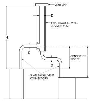
| Table 504.3(2) is used when sizing single-wall vent connectors attached to a Type B double-wall common vent. Note: Each appliance may be either Category I draft hood equipped or fanassisted type. |
FIGURE B-7
VENT SYSTEM SERVING TWO OR MORE APPLIANCES
WITH TYPE B DOUBLE-WALL VENT AND
SINGLE-WALL METAL VENT CONNECTORS
TABLE 504.3(2)
TYPE B DOUBLE-WALL VENT
| Number of Appliances | Two or more |
| Appliance Type | Category I |
| Appliance Vent Connection | Single-wall metal connector |
| VENT CONNECTOR CAPACITY | |||||||||||||||||||||||||
| VENT HEIGHT (H) (feet) |
CONNECTOR RISE (R) (feet) |
SINGLE-WALL METAL VENT CONNECTOR DIAMETER—(D) inches | |||||||||||||||||||||||
| 3 | 4 | 5 | 6 | 7 | 8 | 9 | 10 | ||||||||||||||||||
| APPLIANCE INPUT RATING LIMITS IN THOUSANDS OF BTU/H | |||||||||||||||||||||||||
| FAN | NAT | FAN | NAT | FAN | NAT | FAN | NAT | FAN | NAT | FAN | NAT | FAN | NAT | FAN | NAT | ||||||||||
| Min | Max | Max | Min | Max | Max | Min | Max | Max | Min | Max | Max | Min | Max | Max | Min | Max | Max | Min | Max | Max | Min | Max | Max | ||
| 6 | 1 | NA | NA | 26 | NA | NA | 46 | NA | NA | 71 | NA | NA | 102 | 207 | 223 | 140 | 262 | 293 | 183 | 325 | 373 | 234 | 447 | 463 | 286 |
| 2 | NA | NA | 31 | NA | NA | 55 | NA | NA | 85 | 168 | 182 | 123 | 215 | 251 | 167 | 271 | 331 | 219 | 334 | 422 | 281 | 458 | 524 | 344 | |
| 3 | NA | NA | 34 | NA | NA | 62 | 121 | 131 | 95 | 175 | 198 | 138 | 222 | 273 | 188 | 279 | 361 | 247 | 344 | 462 | 316 | 468 | 574 | 385 | |
| 8 | 1 | NA | NA | 27 | NA | NA | 48 | NA | NA | 75 | NA | NA | 106 | 226 | 240 | 145 | 285 | 316 | 191 | 352 | 403 | 244 | 481 | 502 | 299 |
| 2 | NA | NA | 32 | NA | NA | 57 | 125 | 126 | 89 | 184 | 193 | 127 | 234 | 266 | 173 | 293 | 353 | 228 | 360 | 450 | 292 | 492 | 560 | 355 | |
| 3 | NA | NA | 35 | NA | NA | 64 | 130 | 138 | 100 | 191 | 208 | 144 | 241 | 287 | 197 | 302 | 381 | 256 | 370 | 489 | 328 | 501 | 609 | 400 | |
| 10 | 1 | NA | NA | 28 | NA | NA | 50 | 119 | 121 | 77 | 182 | 186 | 110 | 240 | 253 | 150 | 302 | 335 | 196 | 372 | 429 | 252 | 506 | 534 | 308 |
| 2 | NA | NA | 33 | 84 | 85 | 59 | 124 | 134 | 91 | 189 | 203 | 132 | 248 | 278 | 183 | 311 | 369 | 235 | 381 | 473 | 302 | 517 | 589 | 368 | |
| 3 | NA | NA | 36 | 89 | 91 | 67 | 129 | 144 | 102 | 197 | 217 | 148 | 257 | 299 | 203 | 320 | 398 | 265 | 391 | 511 | 339 | 528 | 637 | 413 | |
| 15 | 1 | NA | NA | 29 | 79 | 87 | 52 | 116 | 138 | 81 | 177 | 214 | 116 | 238 | 291 | 158 | 312 | 380 | 208 | 397 | 482 | 266 | 556 | 596 | 324 |
| 2 | NA | NA | 34 | 83 | 94 | 62 | 121 | 150 | 97 | 185 | 230 | 138 | 246 | 314 | 189 | 321 | 411 | 248 | 407 | 522 | 317 | 568 | 646 | 387 | |
| 3 | NA | NA | 39 | 87 | 100 | 70 | 127 | 160 | 109 | 193 | 243 | 157 | 255 | 333 | 215 | 331 | 438 | 281 | 418 | 557 | 360 | 579 | 690 | 437 | |
| 20 | 1 | 49 | 56 | 30 | 78 | 97 | 54 | 115 | 152 | 84 | 175 | 238 | 120 | 233 | 325 | 165 | 306 | 425 | 217 | 390 | 538 | 276 | 546 | 664 | 336 |
| 2 | 52 | 59 | 36 | 82 | 103 | 64 | 120 | 163 | 101 | 182 | 252 | 144 | 243 | 346 | 197 | 317 | 453 | 259 | 400 | 574 | 331 | 558 | 709 | 403 | |
| 3 | 55 | 62 | 40 | 87 | 107 | 72 | 125 | 172 | 113 | 190 | 264 | 164 | 252 | 363 | 223 | 326 | 476 | 294 | 412 | 607 | 375 | 570 | 750 | 457 | |
| 30 | 1 | 47 | 60 | 31 | 77 | 110 | 57 | 112 | 175 | 89 | 169 | 278 | 129 | 226 | 380 | 175 | 296 | 497 | 230 | 378 | 630 | 294 | 528 | 779 | 358 |
| 2 | 51 | 62 | 37 | 81 | 115 | 67 | 117 | 185 | 106 | 177 | 290 | 152 | 236 | 397 | 208 | 307 | 521 | 274 | 389 | 662 | 349 | 541 | 819 | 425 | |
| 3 | 54 | 64 | 42 | 85 | 119 | 76 | 122 | 193 | 120 | 185 | 300 | 172 | 244 | 412 | 235 | 316 | 542 | 309 | 400 | 690 | 394 | 555 | 855 | 482 | |
| 50 | 1 | 46 | 69 | 34 | 75 | 128 | 60 | 109 | 207 | 96 | 162 | 336 | 137 | 217 | 460 | 188 | 284 | 604 | 245 | 364 | 768 | 314 | 507 | 951 | 384 |
| 2 | 49 | 71 | 40 | 79 | 132 | 72 | 114 | 215 | 113 | 170 | 345 | 164 | 226 | 473 | 223 | 294 | 623 | 293 | 376 | 793 | 375 | 520 | 983 | 458 | |
| 3 | 52 | 72 | 45 | 83 | 136 | 82 | 119 | 221 | 123 | 178 | 353 | 186 | 235 | 486 | 252 | 304 | 640 | 331 | 387 | 816 | 423 | 535 | 1,013 | 518 | |
| 100 | 1 | 45 | 79 | 34 | 71 | 150 | 61 | 104 | 249 | 98 | 153 | 424 | 140 | 205 | 585 | 192 | 269 | 774 | 249 | 345 | 993 | 321 | 476 | 1,236 | 393 |
| 2 | 48 | 80 | 41 | 75 | 153 | 73 | 110 | 255 | 115 | 160 | 428 | 167 | 212 | 593 | 228 | 279 | 788 | 299 | 358 | 1,011 | 383 | 490 | 1,259 | 469 | |
| 3 | 51 | 81 | 46 | 79 | 157 | 85 | 114 | 260 | 129 | 168 | 433 | 190 | 222 | 603 | 256 | 289 | 801 | 339 | 368 | 1,027 | 431 | 506 | 1,280 | 527 | |
| COMMON VENT CAPACITY | |||||||||||||||||||||
| VENT HEIGHT (H) (feet) |
TYPE B DOUBLE-WALL COMMON VENT DIAMETER—(D) inches | ||||||||||||||||||||
| 4 | 5 | 6 | 7 | 8 | 9 | 10 | |||||||||||||||
| COMBINED APPLIANCE INPUT RATING IN THOUSANDS OF BTU/H | |||||||||||||||||||||
| FAN +FAN | FAN +NAT | NAT +NAT | FAN +FAN | FAN +NAT | NAT +NAT | FAN +FAN | FAN +NAT | NAT +NAT | FAN +FAN | FAN +NAT | NAT +NAT | FAN +FAN | FAN +NAT | NAT +NAT | FAN +FAN | FAN +NAT | NAT +NAT | FAN +FAN | FAN +NAT | NAT +NAT | |
| 6 | NA | 78 | 64 | NA | 113 | 99 | 200 | 158 | 144 | 304 | 244 | 196 | 398 | 310 | 257 | 541 | 429 | 332 | 665 | 515 | 407 |
| 8 | NA | 87 | 71 | NA | 126 | 111 | 218 | 173 | 159 | 331 | 269 | 218 | 436 | 342 | 285 | 592 | 473 | 373 | 730 | 569 | 460 |
| 10 | NA | 94 | 76 | 163 | 137 | 120 | 237 | 189 | 174 | 357 | 292 | 236 | 467 | 369 | 309 | 638 | 512 | 398 | 787 | 617 | 487 |
| 15 | 121 | 108 | 88 | 189 | 159 | 140 | 275 | 221 | 200 | 416 | 343 | 274 | 544 | 434 | 357 | 738 | 599 | 456 | 905 | 718 | 553 |
| 20 | 131 | 118 | 98 | 208 | 177 | 156 | 305 | 247 | 223 | 463 | 383 | 302 | 606 | 487 | 395 | 824 | 673 | 512 | 1,013 | 808 | 626 |
| 30 | 145 | 132 | 113 | 236 | 202 | 180 | 350 | 286 | 257 | 533 | 446 | 349 | 703 | 570 | 459 | 958 | 790 | 593 | 1,183 | 952 | 723 |
| 50 | 159 | 145 | 128 | 268 | 233 | 208 | 406 | 337 | 296 | 622 | 529 | 410 | 833 | 686 | 535 | 1,139 | 954 | 689 | 1,418 | 1,157 | 838 |
| 100 | 166 | 153 | NA | 297 | 263 | NA | 469 | 398 | NA | 726 | 633 | 464 | 999 | 846 | 606 | 1,378 | 1,185 | 780 | 1,741 | 1,459 | 948 |
| For SI: 1 inch = 25.4 mm, 1 foot = 304.8 mm, 1 British thermal unit per hour = 0.2931 W. |
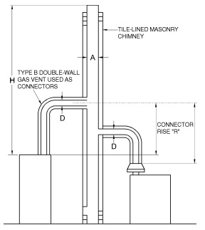
| Table 504.3(3) is used when sizing Type B double-wall vent connectors attached to a tile-lined masonry chimney. Note: “A” is the equivalent cross-sectional area of the tile liner. Note: Each appliance may be either Category I draft hood equipped or fanassisted type. |
FIGURE B-8
MASONRY CHIMNEY SERVING TWO OR MORE APPLIANCES
WITH TYPE B DOUBLE-WALL VENT CONNECTOR
TABLE 504.3(3)
MASONRY CHIMNEY
| Number of Appliances | Two or more |
| Appliance Type | Category I |
| Appliance Vent Connection | Type B double-wall connector |
| VENT CONNECTOR CAPACITY | |||||||||||||||||||||||||
| VENT HEIGHT (H) (feet) |
CONNECTOR RISE (R) (feet) |
TYPE B DOUBLE-WALL VENT CONNECTOR DIAMETER—(D) inches | |||||||||||||||||||||||
| 3 | 4 | 5 | 6 | 7 | 8 | 9 | 10 | ||||||||||||||||||
| APPLIANCE INPUT RATING LIMITS IN THOUSANDS OF BTU/H | |||||||||||||||||||||||||
| FAN | NAT | FAN | NAT | FAN | NAT | FAN | NAT | FAN | NAT | FAN | NAT | FAN | NAT | FAN | NAT | ||||||||||
| Min | Max | Max | Min | Max | Max | Min | Max | Max | Min | Max | Max | Min | Max | Max | Min | Max | Max | Min | Max | Max | Min | Max | Max | ||
| 6 | 1 | 24 | 33 | 21 | 39 | 62 | 40 | 52 | 106 | 67 | 65 | 194 | 101 | 87 | 274 | 141 | 104 | 370 | 201 | 124 | 479 | 253 | 145 | 599 | 319 |
| 2 | 26 | 43 | 28 | 41 | 79 | 52 | 53 | 133 | 85 | 67 | 230 | 124 | 89 | 324 | 173 | 107 | 436 | 232 | 127 | 562 | 300 | 148 | 694 | 378 | |
| 3 | 27 | 49 | 34 | 42 | 92 | 61 | 55 | 155 | 97 | 69 | 262 | 143 | 91 | 369 | 203 | 109 | 491 | 270 | 129 | 633 | 349 | 151 | 795 | 439 | |
| 8 | 1 | 24 | 39 | 22 | 39 | 72 | 41 | 55 | 117 | 69 | 71 | 213 | 105 | 94 | 304 | 148 | 113 | 414 | 210 | 134 | 539 | 267 | 156 | 682 | 335 |
| 2 | 26 | 47 | 29 | 40 | 87 | 53 | 57 | 140 | 86 | 73 | 246 | 127 | 97 | 350 | 179 | 116 | 473 | 240 | 137 | 615 | 311 | 160 | 776 | 394 | |
| 3 | 27 | 52 | 34 | 42 | 97 | 62 | 59 | 159 | 98 | 75 | 269 | 145 | 99 | 383 | 206 | 119 | 517 | 276 | 139 | 672 | 358 | 163 | 848 | 452 | |
| 10 | 1 | 24 | 42 | 22 | 38 | 80 | 42 | 55 | 130 | 71 | 74 | 232 | 108 | 101 | 324 | 153 | 120 | 444 | 216 | 142 | 582 | 277 | 165 | 739 | 348 |
| 2 | 26 | 50 | 29 | 40 | 93 | 54 | 57 | 153 | 87 | 76 | 261 | 129 | 103 | 366 | 184 | 123 | 498 | 247 | 145 | 652 | 321 | 168 | 825 | 407 | |
| 3 | 27 | 55 | 35 | 41 | 105 | 63 | 58 | 170 | 100 | 78 | 284 | 148 | 106 | 397 | 209 | 126 | 540 | 281 | 147 | 705 | 366 | 171 | 893 | 463 | |
| 15 | 1 | 24 | 48 | 23 | 38 | 93 | 44 | 54 | 154 | 74 | 72 | 277 | 114 | 100 | 384 | 164 | 125 | 511 | 229 | 153 | 658 | 297 | 184 | 824 | 375 |
| 2 | 25 | 55 | 31 | 39 | 105 | 55 | 56 | 174 | 89 | 74 | 299 | 134 | 103 | 419 | 192 | 128 | 558 | 260 | 156 | 718 | 339 | 187 | 900 | 432 | |
| 3 | 26 | 59 | 35 | 41 | 115 | 64 | 57 | 189 | 102 | 76 | 319 | 153 | 105 | 448 | 215 | 131 | 597 | 292 | 159 | 760 | 382 | 190 | 960 | 486 | |
| 20 | 1 | 24 | 52 | 24 | 37 | 102 | 46 | 53 | 172 | 77 | 71 | 313 | 119 | 98 | 437 | 173 | 123 | 584 | 239 | 150 | 752 | 312 | 180 | 943 | 397 |
| 2 | 25 | 58 | 31 | 39 | 114 | 56 | 55 | 190 | 91 | 73 | 335 | 138 | 101 | 467 | 199 | 126 | 625 | 270 | 153 | 805 | 354 | 184 | 1,011 | 452 | |
| 3 | 26 | 63 | 35 | 40 | 123 | 65 | 57 | 204 | 104 | 75 | 353 | 157 | 104 | 493 | 222 | 129 | 661 | 301 | 156 | 851 | 396 | 187 | 1,067 | 505 | |
| 30 | 1 | 24 | 54 | 25 | 37 | 111 | 48 | 52 | 192 | 82 | 69 | 357 | 127 | 96 | 504 | 187 | 119 | 680 | 255 | 145 | 883 | 337 | 175 | 1,115 | 432 |
| 2 | 25 | 60 | 32 | 38 | 122 | 58 | 54 | 208 | 95 | 72 | 376 | 145 | 99 | 531 | 209 | 122 | 715 | 287 | 149 | 928 | 378 | 179 | 1,171 | 484 | |
| 3 | 26 | 64 | 36 | 40 | 131 | 66 | 56 | 221 | 107 | 74 | 392 | 163 | 101 | 554 | 233 | 125 | 746 | 317 | 152 | 968 | 418 | 182 | 1,220 | 535 | |
| 50 | 1 | 23 | 51 | 25 | 36 | 116 | 51 | 51 | 209 | 89 | 67 | 405 | 143 | 92 | 582 | 213 | 115 | 798 | 294 | 140 | 1,049 | 392 | 168 | 1,334 | 506 |
| 2 | 24 | 59 | 32 | 37 | 127 | 61 | 53 | 225 | 102 | 70 | 421 | 161 | 95 | 604 | 235 | 118 | 827 | 326 | 143 | 1,085 | 433 | 172 | 1,379 | 558 | |
| 3 | 26 | 64 | 36 | 39 | 135 | 69 | 55 | 237 | 115 | 72 | 435 | 80 | 98 | 624 | 260 | 121 | 854 | 357 | 147 | 1,118 | 474 | 176 | 1,421 | 611 | |
| 100 | 1 | 23 | 46 | 24 | 35 | 108 | 50 | 49 | 208 | 92 | 65 | 428 | 155 | 88 | 640 | 237 | 109 | 907 | 334 | 134 | 1,222 | 454 | 161 | 1,589 | 596 |
| 2 | 24 | 53 | 31 | 37 | 120 | 60 | 51 | 224 | 105 | 67 | 444 | 174 | 92 | 660 | 260 | 113 | 933 | 368 | 138 | 1,253 | 497 | 165 | 1,626 | 651 | |
| 3 | 25 | 59 | 35 | 38 | 130 | 68 | 53 | 237 | 118 | 69 | 458 | 193 | 94 | 679 | 285 | 116 | 956 | 399 | 141 | 1,282 | 540 | 169 | 1,661 | 705 | |
| COMMON VENT CAPACITY | ||||||||||||||||||||||||
| VENT HEIGHT (H)(feet) | MINIMUM INTERNAL AREA OF MASONRY CHIMNEY FLUE (square inches) | |||||||||||||||||||||||
| 12 | 19 | 28 | 38 | 50 | 63 | 78 | 113 | |||||||||||||||||
| COMBINED APPLIANCE INPUT RATING IN THOUSANDS OF BTU/H | ||||||||||||||||||||||||
| FAN +FAN | FAN +NAT | NAT +NAT | FAN +FAN | FAN +NAT | NAT +NAT | FAN +FAN | FAN +NAT | NAT +NAT | FAN +FAN | FAN +NAT | NAT +NAT | FAN +FAN | FAN +NAT | NAT +NAT | FAN +FAN | FAN +NAT | NAT +NAT | FAN +FAN | FAN +NAT | NAT +NAT | FAN +FAN | FAN +NAT | NAT +NAT | |
| 6 | NA | 74 | 25 | NA | 119 | 46 | NA | 178 | 71 | NA | 257 | 103 | NA | 351 | 143 | NA | 458 | 188 | NA | 582 | 246 | 1,041 | 853 | NA |
| 8 | NA | 80 | 28 | NA | 130 | 53 | NA | 193 | 82 | NA | 279 | 119 | NA | 384 | 163 | NA | 501 | 218 | 724 | 636 | 278 | 1,144 | 937 | 408 |
| 10 | NA | 84 | 31 | NA | 138 | 56 | NA | 207 | 90 | NA | 299 | 131 | NA | 409 | 177 | 606 | 538 | 236 | 776 | 686 | 302 | 1,226 | 1,010 | 454 |
| 15 | NA | NA | 36 | NA | 152 | 67 | NA | 233 | 106 | NA | 334 | 152 | 523 | 467 | 212 | 682 | 611 | 283 | 874 | 781 | 365 | 1,374 | 1,156 | 546 |
| 20 | NA | NA | 41 | NA | NA | 75 | NA | 250 | 122 | NA | 368 | 172 | 565 | 508 | 243 | 742 | 668 | 325 | 955 | 858 | 419 | 1,513 | 1,286 | 648 |
| 30 | NA | NA | NA | NA | NA | NA | NA | 270 | 137 | NA | 404 | 198 | 615 | 564 | 278 | 816 | 747 | 381 | 1,062 | 969 | 496 | 1,702 | 1,473 | 749 |
| 50 | NA | NA | NA | NA | NA | NA | NA | NA | NA | NA | NA | NA | NA | 620 | 328 | 879 | 831 | 461 | 1,165 | 1,089 | 606 | 1,905 | 1,692 | 922 |
| 100 | NA | NA | NA | NA | NA | NA | NA | NA | NA | NA | NA | NA | NA | NA | 348 | NA | NA | 499 | NA | NA | 669 | 2,053 | 1,921 | 1,058 |
| For SI:1 inch = 25.4 mm, 1 square inch = 645.16 mm2, 1 foot = 304.8 mm, 1 British thermal unit per hour = 0.2931 W. |
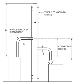
| Table 504.3(4) is used when sizing single-wall metal vent connectors attached to a tile-lined masonry chimney. Note: “A” is the equivalent cross-sectional area of the tile liner. Note: Each appliance may be either Category I draft hood equipped or fanassisted type. |
FIGURE B-9
MASONRY CHIMNEY SERVING TWO OR MORE APPLIANCES
WITH SINGLE-WALL METAL VENT CONNECTORS
TABLE 504.3(4)
MASONRY CHIMNEY
| Number of Appliances | Two or more |
| Appliance Type | Category I |
| Appliance Vent Connection | Single-wall metal connector |
| VENT CONNECTOR CAPACITY | |||||||||||||||||||||||||
| VENT HEIGHT (H) (feet) |
CONNECTOR RISE (R) (feet) |
SINGLE-WALL METAL VENT CONNECTOR DIAMETER—(D) inches | |||||||||||||||||||||||
| 3 | 4 | 5 | 6 | 7 | 8 | 9 | 10 | ||||||||||||||||||
| APPLIANCE INPUT RATING LIMITS IN THOUSANDS OF BTU/H | |||||||||||||||||||||||||
| FAN | NAT | FAN | NAT | FAN | NAT | FAN | NAT | FAN | NAT | FAN | NAT | FAN | NAT | FAN | NAT | ||||||||||
| Min | Max | Max | Min | Max | Max | Min | Max | Max | Min | Max | Max | Min | Max | Max | Min | Max | Max | Min | Max | Max | Min | Max | Max | ||
| 6 | 1 | NA | NA | 21 | NA | NA | 39 | NA | NA | 66 | 179 | 191 | 100 | 231 | 271 | 140 | 292 | 366 | 200 | 362 | 474 | 252 | 499 | 594 | 316 |
| 2 | NA | NA | 28 | NA | NA | 52 | NA | NA | 84 | 186 | 227 | 123 | 239 | 321 | 172 | 301 | 432 | 231 | 373 | 557 | 299 | 509 | 696 | 376 | |
| 3 | NA | NA | 34 | NA | NA | 61 | 134 | 153 | 97 | 193 | 258 | 142 | 247 | 365 | 202 | 309 | 491 | 269 | 381 | 634 | 348 | 519 | 793 | 437 | |
| 8 | 1 | NA | NA | 21 | NA | NA | 40 | NA | NA | 68 | 195 | 208 | 103 | 250 | 298 | 146 | 313 | 407 | 207 | 387 | 530 | 263 | 529 | 672 | 331 |
| 2 | NA | NA | 28 | NA | NA | 52 | 137 | 139 | 85 | 202 | 240 | 125 | 258 | 343 | 177 | 323 | 465 | 238 | 397 | 607 | 309 | 540 | 766 | 391 | |
| 3 | NA | NA | 34 | NA | NA | 62 | 143 | 156 | 98 | 210 | 264 | 145 | 266 | 376 | 205 | 332 | 509 | 274 | 407 | 663 | 356 | 551 | 838 | 450 | |
| 10 | 1 | NA | NA | 22 | NA | NA | 41 | 130 | 151 | 70 | 202 | 225 | 106 | 267 | 316 | 151 | 333 | 434 | 213 | 410 | 571 | 273 | 558 | 727 | 343 |
| 2 | NA | NA | 29 | NA | NA | 53 | 136 | 150 | 86 | 210 | 255 | 128 | 276 | 358 | 181 | 343 | 489 | 244 | 420 | 640 | 317 | 569 | 813 | 403 | |
| 3 | NA | NA | 34 | 97 | 102 | 62 | 143 | 166 | 99 | 217 | 277 | 147 | 284 | 389 | 207 | 352 | 530 | 279 | 430 | 694 | 363 | 580 | 880 | 459 | |
| 15 | 1 | NA | NA | 23 | NA | NA | 43 | 129 | 151 | 73 | 199 | 271 | 112 | 268 | 376 | 161 | 349 | 502 | 225 | 445 | 646 | 291 | 623 | 808 | 366 |
| 2 | NA | NA | 30 | 92 | 103 | 54 | 135 | 170 | 88 | 207 | 295 | 132 | 277 | 411 | 189 | 359 | 548 | 256 | 456 | 706 | 334 | 634 | 884 | 424 | |
| 3 | NA | NA | 34 | 96 | 112 | 63 | 141 | 185 | 101 | 215 | 315 | 151 | 286 | 439 | 213 | 368 | 586 | 289 | 466 | 755 | 378 | 646 | 945 | 479 | |
| 20 | 1 | NA | NA | 23 | 87 | 99 | 45 | 128 | 167 | 76 | 197 | 303 | 117 | 265 | 425 | 169 | 345 | 569 | 235 | 439 | 734 | 306 | 614 | 921 | 347 |
| 2 | NA | NA | 30 | 91 | 111 | 55 | 134 | 185 | 90 | 205 | 325 | 136 | 274 | 455 | 195 | 355 | 610 | 266 | 450 | 787 | 348 | 627 | 986 | 443 | |
| 3 | NA | NA | 35 | 96 | 119 | 64 | 140 | 199 | 103 | 213 | 343 | 154 | 282 | 481 | 219 | 365 | 644 | 298 | 461 | 831 | 391 | 639 | 1,042 | 496 | |
| 30 | 1 | NA | NA | 24 | 86 | 108 | 47 | 126 | 187 | 80 | 193 | 347 | 124 | 259 | 492 | 183 | 338 | 665 | 250 | 430 | 864 | 330 | 600 | 1,089 | 421 |
| 2 | NA | NA | 31 | 91 | 119 | 57 | 132 | 203 | 93 | 201 | 366 | 142 | 269 | 518 | 205 | 348 | 699 | 282 | 442 | 908 | 372 | 613 | 1,145 | 473 | |
| 3 | NA | NA | 35 | 95 | 127 | 65 | 138 | 216 | 105 | 209 | 381 | 160 | 277 | 540 | 229 | 358 | 729 | 312 | 452 | 946 | 412 | 626 | 1,193 | 524 | |
| 50 | 1 | NA | NA | 24 | 85 | 113 | 50 | 124 | 204 | 87 | 188 | 392 | 139 | 252 | 567 | 208 | 328 | 778 | 287 | 417 | 1,022 | 383 | 582 | 1,302 | 492 |
| 2 | NA | NA | 31 | 89 | 123 | 60 | 130 | 218 | 100 | 196 | 408 | 158 | 262 | 588 | 230 | 339 | 806 | 320 | 429 | 1,058 | 425 | 596 | 1,346 | 545 | |
| 3 | NA | NA | 35 | 94 | 131 | 68 | 136 | 231 | 112 | 205 | 422 | 176 | 271 | 607 | 255 | 349 | 831 | 351 | 440 | 1,090 | 466 | 610 | 1,386 | 597 | |
| 100 | 1 | NA | NA | 23 | 84 | 104 | 49 | 122 | 200 | 89 | 182 | 410 | 151 | 243 | 617 | 232 | 315 | 875 | 328 | 402 | 1,181 | 444 | 560 | 1,537 | 580 |
| 2 | NA | NA | 30 | 88 | 115 | 59 | 127 | 215 | 102 | 190 | 425 | 169 | 253 | 636 | 254 | 326 | 899 | 361 | 415 | 1,210 | 488 | 575 | 1,570 | 634 | |
| 3 | NA | NA | 34 | 93 | 124 | 67 | 133 | 228 | 115 | 199 | 438 | 188 | 262 | 654 | 279 | 337 | 921 | 392 | 427 | 1,238 | 529 | 589 | 1,604 | 687 | |
| COMMON VENT CAPACITY | ||||||||||||||||||||||||
| VENT HEIGHT (H) (feet) |
MINIMUM INTERNAL AREA OF MASONRY CHIMNEY FLUE (square inches) | |||||||||||||||||||||||
| 12 | 19 | 28 | 38 | 50 | 63 | 78 | 113 | |||||||||||||||||
| COMBINED APPLIANCE INPUT RATING IN THOUSANDS OF BTU/H | ||||||||||||||||||||||||
| FAN +FAN | FAN +NAT | NAT +NAT | FAN +FAN | FAN +NAT | NAT +NAT | FAN +FAN | FAN +NAT | NAT +NAT | FAN +FAN | FAN +NAT | NAT +NAT | FAN +FAN | FAN +NAT | NAT +NAT | FAN +FAN | FAN +NAT | NAT +NAT | FAN +FAN | FAN +NAT | NAT +NAT | FAN +FAN | FAN +NAT | NAT +NAT | |
| 6 | NA | NA | 25 | NA | 118 | 45 | NA | 176 | 71 | NA | 255 | 102 | NA | 348 | 142 | NA | 455 | 187 | NA | 579 | 245 | NA | 846 | NA |
| 8 | NA | NA | 28 | NA | 128 | 52 | NA | 190 | 81 | NA | 276 | 118 | NA | 380 | 162 | NA | 497 | 217 | NA | 633 | 277 | 1,136 | 928 | 405 |
| 10 | NA | NA | 31 | NA | 136 | 56 | NA | 205 | 89 | NA | 295 | 129 | NA | 405 | 175 | NA | 532 | 234 | 171 | 680 | 300 | 1,216 | 1,000 | 450 |
| 15 | NA | NA | 36 | NA | NA | 66 | NA | 230 | 105 | NA | 335 | 150 | NA | 400 | 210 | 677 | 602 | 280 | 866 | 772 | 360 | 1,359 | 1,139 | 540 |
| 20 | NA | NA | NA | NA | NA | 74 | NA | 247 | 120 | NA | 362 | 170 | NA | 503 | 240 | 765 | 661 | 321 | 947 | 849 | 415 | 1,495 | 1,264 | 640 |
| 30 | NA | NA | NA | NA | NA | NA | NA | NA | 135 | NA | 398 | 195 | NA | 558 | 275 | 808 | 739 | 377 | 1,052 | 957 | 490 | 1,682 | 1,447 | 740 |
| 50 | NA | NA | NA | NA | NA | NA | NA | NA | NA | NA | NA | NA | NA | 612 | 325 | NA | 821 | 456 | 1,152 | 1,076 | 600 | 1,879 | 1,672 | 910 |
| 100 | NA | NA | NA | NA | NA | NA | NA | NA | NA | NA | NA | NA | NA | NA | NA | NA | NA | 494 | NA | NA | 663 | 2,006 | 1,885 | 1,046 |
| For SI: 1 inch = 25.4 mm, 1 square inch = 645.16 mm2, 1 foot = 304.8 mm, 1 British thermal unit per hour = 0.2931 W. |
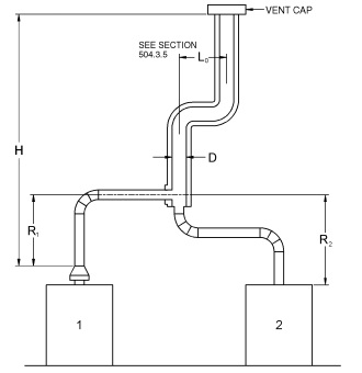
| Asbestos cement Type B or single-wall metal pipe vent serving two or more draft-hood-equipped appliances [see Table 504.3(5)]. |
FIGURE B-10
ASBESTOS CEMENT TYPE B OR SINGLE-WALL
METAL VENT SYSTEM SERVING TWO OR MORE
DRAFT-HOOD-EQUIPPED APPLIANCES
TABLE 504.3(5)
SINGLE-WALL METAL PIPE OR TYPE ASBESTOS CEMENT VENT
| Number of Appliances | Two or more |
| Appliance Type | Draft hood-equipped |
| Appliance Vent Connection | Direct to pipe or vent |
| VENT CONNECTOR CAPACITY | |||||||
| TOTAL VENT HEIGHT (H) (feet) |
CONNECTOR RISE (R) (feet) |
VENT CONNECTOR DIAMETER—(D) inches | |||||
| 3 | 4 | 5 | 6 | 7 | 8 | ||
| MAXIMUM APPLIANCE INPUT RATING IN THOUSANDS OF BTU/H | |||||||
| 6-8 | 1 | 21 | 40 | 68 | 102 | 146 | 205 |
| 2 | 28 | 53 | 86 | 124 | 178 | 235 | |
| 3 | 34 | 61 | 98 | 147 | 204 | 275 | |
| 15 | 1 | 23 | 44 | 77 | 117 | 179 | 240 |
| 2 | 30 | 56 | 92 | 134 | 194 | 265 | |
| 3 | 35 | 64 | 102 | 155 | 216 | 298 | |
| 30 and up | 1 | 25 | 49 | 84 | 129 | 190 | 270 |
| 2 | 31 | 58 | 97 | 145 | 211 | 295 | |
| 3 | 36 | 68 | 107 | 164 | 232 | 321 | |
| COMMON VENT CAPACITY | |||||||
| TOTAL VENT HEIGHT (H) (feet) |
COMMON VENT DIAMETER—(D) inches | ||||||
| 4 | 5 | 6 | 7 | 8 | 10 | 12 | |
| COMBINED APPLIANCE INPUT RATING IN THOUSANDS OF BTU/H | |||||||
| 6 | 48 | 78 | 111 | 155 | 205 | 320 | NA |
| 8 | 55 | 89 | 128 | 175 | 234 | 365 | 505 |
| 10 | 59 | 95 | 136 | 190 | 250 | 395 | 560 |
| 15 | 71 | 115 | 168 | 228 | 305 | 480 | 690 |
| 20 | 80 | 129 | 186 | 260 | 340 | 550 | 790 |
| 30 | NA | 147 | 215 | 300 | 400 | 650 | 940 |
| 50 | NA | NA | NA | 360 | 490 | 810 | 1,190 |
| For SI: 1 inch = 25.4 mm, 1 foot = 304.8 mm, 1 British thermal unit per hour = 0.2931 W. |
TABLE 504.3(6a)
EXTERIOR MASONRY CHIMNEY
| Number of Appliances |
Two or more |
| Appliance Type |
NAT + NAT |
| Appliance Vent Connection |
Type B double-wall connector |
| Combined Appliance Maximum Input Rating in Thousands of Btu per Hour |
||||||||
| VENT HEIGHT (feet) |
INTERNAL AREA OF CHIMNEY (square inches) | |||||||
| 12 | 19 | 28 | 38 | 50 | 63 | 78 | 113 | |
| 6 | 25 | 46 | 71 | 103 | 143 | 188 | 246 | NA |
| 8 | 28 | 53 | 82 | 119 | 163 | 218 | 278 | 408 |
| 10 | 31 | 56 | 90 | 131 | 177 | 236 | 302 | 454 |
| 15 | NA | 67 | 106 | 152 | 212 | 283 | 365 | 546 |
| 20 | NA | NA | NA | NA | NA | 325 | 419 | 648 |
| 30 | NA | NA | NA | NA | NA | NA | 496 | 749 |
| 50 | NA | NA | NA | NA | NA | NA | NA | 922 |
| 100 | NA | NA | NA | NA | NA | NA | NA | NA |
TABLE 504.3(6b)
EXTERIOR MASONRY CHIMNEY
| Number of Appliances |
Two or more |
| Appliance Type |
NAT + NAT |
| Appliance Vent Connection |
Type B double-wall connector |
| Minimum Allowable Input Rating of Space-heating Appliance in Thousands of Btu per Hour |
||||||||
| VENT HEIGHT (feet) |
INTERNAL AREA OF CHIMNEY (square inches) | |||||||
| 12 | 19 | 28 | 38 | 50 | 63 | 78 | 113 | |
| 37°F or Greater |
Local 99% Winter Design Temperature: 37°F or Greater | |||||||
| 6 | 0 | 0 | 0 | 0 | 0 | 0 | 0 | NA |
| 8 | 0 | 0 | 0 | 0 | 0 | 0 | 0 | 0 |
| 10 | 0 | 0 | 0 | 0 | 0 | 0 | 0 | 0 |
| 15 | NA | 0 | 0 | 0 | 0 | 0 | 0 | 0 |
| 20 | NA | NA | NA | NA | NA | 184 | 0 | 0 |
| 30 | NA | NA | NA | NA | NA | 393 | 334 | 0 |
| 50 | NA | NA | NA | NA | NA | NA | NA | 579 |
| 100 | NA | NA | NA | NA | NA | NA | NA | NA |
| 27 to 36°F |
Local 99% Winter Design Temperature: 27 to 36°F | |||||||
| 6 | 0 | 0 | 68 | NA | NA | 180 | 212 | NA |
| 8 | 0 | 0 | 82 | NA | NA | 187 | 214 | 263 |
| 10 | 0 | 51 | NA | NA | NA | 201 | 225 | 265 |
| 15 | NA | NA | NA | NA | NA | 253 | 274 | 305 |
| 20 | NA | NA | NA | NA | NA | 307 | 330 | 362 |
| 30 | NA | NA | NA | NA | NA | NA | 445 | 485 |
| 50 | NA | NA | NA | NA | NA | NA | NA | 763 |
| 100 | NA | NA | NA | NA | NA | NA | NA | NA |
TABLE 504.3(6b)
EXTERIOR MASONRY CHIMNEY-continued
| Minimum Allowable Input Rating of Space-heating Appliance in Thousands of Btu per Hour |
||||||||
| VENT HEIGHT (feet) |
INTERNAL AREA OF CHIMNEY (square inches) | |||||||
| 12 | 19 | 28 | 38 | 50 | 63 | 78 | 113 | |
| 17 to 26°F | Local 99% Winter Design Temperature: 17 to 26°F | |||||||
| 6 | NA | NA | NA | NA | NA | NA | NA | NA |
| 8 | NA | NA | NA | NA | NA | NA | 264 | 352 |
| 10 | NA | NA | NA | NA | NA | NA | 278 | 358 |
| 15 | NA | NA | NA | NA | NA | NA | 331 | 398 |
| 20 | NA | NA | NA | NA | NA | NA | 387 | 457 |
| 30 | NA | NA | NA | NA | NA | NA | NA | 581 |
| 50 | NA | NA | NA | NA | NA | NA | NA | 862 |
| 100 | NA | NA | NA | NA | NA | NA | NA | NA |
| 5 to 16°F | Local 99% Winter Design Temperature: 5 to 16°F | |||||||
| 6 | NA | NA | NA | NA | NA | NA | NA | NA |
| 8 | NA | NA | NA | NA | NA | NA | NA | NA |
| 10 | NA | NA | NA | NA | NA | NA | NA | 430 |
| 15 | NA | NA | NA | NA | NA | NA | NA | 485 |
| 20 | NA | NA | NA | NA | NA | NA | NA | 547 |
| 30 | NA | NA | NA | NA | NA | NA | NA | 682 |
| 50 | NA | NA | NA | NA | NA | NA | NA | NA |
| 100 | NA | NA | NA | NA | NA | NA | NA | NA |
| 4°F or Lower | Local 99% Winter Design Temperature: 4°F or Lower | |||||||
| Not recommended for any vent configurations | ||||||||
| For SI: °C = (°F – 32)/1.8, 1 inch = 25.4 mm, 1 square inch = 645.16 mm2, 1 foot = 304.8 mm, 1 British thermal unit per hour = 0.2931 W. |
| Note: See Figure B-19 in Appendix B for a map showing local 99 percent winter design temperatures in the United States. |
TABLE 504.3(7a)
EXTERIOR MASONRY CHIMNEY
| Number of Appliances |
Two or more |
| Appliance Type | FAN + NAT |
| Appliance Vent Connection | Type B double-wall connector |
| Combined Appliance Maximum Input Rating in Thousands of Btu per Hour |
||||||||
| VENT HEIGHT (feet) |
INTERNAL AREA OF CHIMNEY (square inches) | |||||||
| 12 | 19 | 28 | 38 | 50 | 63 | 78 | 113 | |
| 6 | 74 | 119 | 178 | 257 | 351 | 458 | 582 | 853 |
| 8 | 80 | 130 | 193 | 279 | 384 | 501 | 636 | 937 |
| 10 | 84 | 138 | 207 | 299 | 409 | 538 | 686 | 1,010 |
| 15 | NA | 152 | 233 | 334 | 467 | 611 | 781 | 1,156 |
| 20 | NA | NA | 250 | 368 | 508 | 668 | 858 | 1,286 |
| 30 | NA | NA | NA | 404 | 564 | 747 | 969 | 1,473 |
| 50 | NA | NA | NA | NA | NA | 831 | 1,089 | 1,692 |
| 100 | NA | NA | NA | NA | NA | NA | NA | 1,921 |
TABLE 504.3(7b)
EXTERIOR MASONRY CHIMNEY
| Number of Appliances |
Two or more |
| Appliance Type | FAN + NAT |
| Appliance Vent Connection | Type B double-wall connector |
| Minimum Allowable Input Rating of Space-heating Appliance in Thousands of Btu per Hour |
||||||||
| VENT HEIGHT (feet) |
INTERNAL AREA OF CHIMNEY (square inches) | |||||||
| 12 | 19 | 28 | 38 | 50 | 63 | 78 | 113 | |
| 37°F or Greater | Local 99% Winter Design Temperature: 37°F or Greater | |||||||
| 6 | 0 | 0 | 0 | 0 | 0 | 0 | 0 | 0 |
| 8 | 0 | 0 | 0 | 0 | 0 | 0 | 0 | 0 |
| 10 | 0 | 0 | 0 | 0 | 0 | 0 | 0 | 0 |
| 15 | NA | 0 | 0 | 0 | 0 | 0 | 0 | 0 |
| 20 | NA | NA | 123 | 190 | 249 | 184 | 0 | 0 |
| 30 | NA | NA | NA | 334 | 398 | 393 | 334 | 0 |
| 50 | NA | NA | NA | NA | NA | 714 | 707 | 579 |
| 100 | NA | NA | NA | NA | NA | NA | NA | 1,600 |
| 27 to 36°F | Local 99% Winter Design Temperature: 27 to 36°F | |||||||
| 6 | 0 | 0 | 68 | 116 | 156 | 180 | 212 | 266 |
| 8 | 0 | 0 | 82 | 127 | 167 | 187 | 214 | 263 |
| 10 | 0 | 51 | 97 | 141 | 183 | 201 | 225 | 265 |
| 15 | NA | 111 | 142 | 183 | 233 | 253 | 274 | 305 |
| 20 | NA | NA | 187 | 230 | 284 | 307 | 330 | 362 |
| 30 | NA | NA | NA | 330 | 319 | 419 | 445 | 485 |
| 50 | NA | NA | NA | NA | NA | 672 | 705 | 763 |
| 100 | NA | NA | NA | NA | NA | NA | NA | 1,554 |
TABLE 504.3(7b)
EXTERIOR MASONRY CHIMNEY—continued
| Minimum Allowable Input Rating of Space-heating Appliance in Thousands of Btu per Hour |
|||||||||
| VENT HEIGHT (feet) |
INTERNAL AREA OF CHIMNEY (square inches) | ||||||||
| 12 | 19 | 28 | 38 | 50 | 63 | 78 | 113 | ||
| 17 to 26°F | Local 99% Winter Design Temperature: 17 to 26°F | ||||||||
| 6 | 0 | 55 | 99 | 141 | 182 | 215 | 259 | 349 | |
| 8 | 52 | 74 | 111 | 154 | 197 | 226 | 264 | 352 | |
| 10 | NA | 90 | 125 | 169 | 214 | 245 | 278 | 358 | |
| 15 | NA | NA | 167 | 212 | 263 | 296 | 331 | 398 | |
| 20 | NA | NA | 212 | 258 | 316 | 352 | 387 | 457 | |
| 30 | NA | NA | NA | 362 | 429 | 470 | 507 | 581 | |
| 50 | NA | NA | NA | NA | NA | 723 | 766 | 862 | |
| 100 | NA | NA | NA | NA | NA | NA | NA | 1,669 | |
| 5 to 16°F | Local 99% Winter Design Temperature: 5 to 16°F | ||||||||
| 6 | NA | 78 | 121 | 166 | 214 | 252 | 301 | 416 | |
| 8 | NA | 94 | 135 | 182 | 230 | 269 | 312 | 423 | |
| 10 | NA | 111 | 149 | 198 | 250 | 289 | 331 | 430 | |
| 15 | NA | NA | 193 | 247 | 305 | 346 | 393 | 485 | |
| 20 | NA | NA | NA | 293 | 360 | 408 | 450 | 547 | |
| 30 | NA | NA | NA | 377 | 450 | 531 | 580 | 682 | |
| 50 | NA | NA | NA | NA | NA | 797 | 853 | 972 | |
| 100 | NA | NA | NA | NA | NA | NA | NA | 1,833 | |
| -10 to 4°F | Local 99% Winter Design Temperature: -10 to 4°F | ||||||||
| 6 | NA | NA | 145 | 196 | 249 | 296 | 349 | 484 | |
| 8 | NA | NA | 159 | 213 | 269 | 320 | 371 | 494 | |
| 10 | NA | NA | 175 | 231 | 292 | 339 | 397 | 513 | |
| 15 | NA | NA | NA | 283 | 351 | 404 | 457 | 586 | |
| 20 | NA | NA | NA | 333 | 408 | 468 | 528 | 650 | |
| 30 | NA | NA | NA | NA | NA | 603 | 667 | 805 | |
| 50 | NA | NA | NA | NA | NA | NA | 955 | 1,003 | |
| 100 | NA | NA | NA | NA | NA | NA | NA | NA | |
| -11°F or Lower |
Local 99% Winter Design Temperature: -11°F or Lower | ||||||||
| Not recommended for any vent configurations | |||||||||
| For SI: °C = (°F – 32)/1.8, 1 inch = 25.4 mm, 1 square inch = 645.16 mm2, 1 foot = 304.8 mm, 1 British thermal unit per hour = 0.2931 W. |
| Note: See Figure B-19 in Appendix B for a map showing local 99 percent winter design temperatures in the United States. |
504.3.1 Vent obstructions.
These venting tables shall not be used where obstructions, as described in Section 503.15, are installed in the venting system. The installation of vents serving listed appliances with vent dampers shall be in accordance with the appliance manufacturer’s instructions or in accordance with the following:
1. The maximum capacity of the vent connector shall be determined using the NAT Max column.
2. The maximum capacity of the vertical vent or chimney shall be determined using the FAN+NAT column when the second appliance is a fan-assisted appliance, or the NAT+NAT column when the second appliance is equipped with a draft hood.
3. The minimum capacity shall be determined as if the appliance were a fan-assisted appliance.
3.1. The minimum capacity of the vent connector shall be determined using the FAN Min column.
3.2. The FAN+FAN column shall be used where the second appliance is a fan-assisted appliance, and the FAN+NAT column shall be used where the second appliance is equipped with a draft hood, to determine whether the vertical vent or chimney configuration is not permitted (NA). Where the vent configuration is NA, the vent configuration shall not be permitted and an alternative venting configuration shall be utilized.
504.3.2 Connector length limit.
The vent connector shall be routed to the vent utilizing the shortest possible route. Except as provided in Section 504.3.3, the maximum vent connector horizontal length shall be 11/2feet for each inch (18 mm per mm) of connector diameter as shown in Table 504.3.2.
TABLE 504.3.2
MAXIMUM VENT CONNECTOR LENGTH
| CONNECTOR DIAMETER (inches) |
CONNECTOR MAXIMUM HORIZONTAL LENGTH (feet) |
| 3 | 41/2 |
| 4 | 6 |
| 5 | 71/2 |
| 6 | 9 |
| 7 | 101/2 |
| 8 | 12 |
| 9 | 131/2 |
| 10 | 15 |
| 12 | 18 |
| 14 | 21 |
| 16 | 24 |
| 18 | 27 |
| 20 | 30 |
| 22 | 33 |
| 24 | 36 |
| For SI: 1 inch = 25.4 mm, 1 foot = 304.8 mm. |
504.3.3 Connectors with longer lengths.
Connectors with longer horizontal lengths than those listed in Section 504.3.2 are permitted under the following conditions:
1. The maximum capacity (FAN Max or NAT Max) of the vent connector shall be reduced 10 percent for each additional multiple of the length allowed by Section 504.3.2. For example, the maximum length listed in Table 504.3.2 for a 4-inch (102 mm) connector is 6 feet (1829 mm). With a connector length greater than 6 feet (1829 mm) but not exceeding 12 feet (3658 mm), the maximum capacity must be reduced by 10 percent (0.90 × maximum vent connector capacity). With a connector length greater than 12 feet (3658 mm) but not exceeding 18 feet (5486 mm), the maximum capacity must be reduced by 20 percent (0.80 × maximum vent capacity).
2. For a connector serving a fan-assisted appliance, the minimum capacity (FAN Min) of the connector shall be determined by referring to the corresponding single appliance table. For Type B double-wall connectors, Table 504.2(1) shall be used. For single-wall connectors, Table 504.2(2) shall be used. The height (H) and lateral (L) shall be measured according to the procedures for a single-appliance vent, as if the other appliances were not present.
504.3.4 Vent connector manifold.
Where the vent connectors are combined prior to entering the vertical portion of the common vent to form a common vent manifold, the size of the common vent manifold and the common vent shall be determined by applying a 10-percent reduction (0.90 × maximum common vent capacity) to the common vent capacity part of the common vent tables. The length of the common vent connector manifold (Lm) shall not exceed 11/2 feet for each inch (18 mm per mm) of common vent connector manifold diameter (D).
504.3.5 Common vertical vent offset.
Where the common vertical vent is offset, the maximum capacity of the common vent shall be reduced in accordance with Section 504.3.6. The horizontal length of the common vent offset (Lo) shall not exceed 11/2 feet for each inch (18 mm per mm) of common vent diameter (D). Where multiple offsets occur in a common vent, the total horizontal length of all offsets combined shall not exceed 11/2 feet for each inch (18 mm per mm) of common vent diameter (D).
504.3.6 Elbows in vents.
For each elbow up to and including 45 degrees (0.79 rad) in the common vent, the maximum common vent capacity listed in the venting tables shall be reduced by 5 percent. For each elbow greater than 45 degrees (0.79 rad) up to and including 90 degrees (1.57 rad), the maximum common vent capacity listed in the venting tables shall be reduced by 10 percent.
504.3.7 Elbows in connectors.
The vent connector capacities listed in the common vent sizing tables include allowance for two 90-degree (1.57 rad) elbows. For each additional elbow up to and including 45 degrees (0.79 rad), the maximum vent connector capacity listed in the venting tables shall be reduced by 5 percent. For each elbow greater than 45 degrees (0.79 rad) up to and including 90 degrees (1.57 rad), the maximum vent connector capacity listed in the venting tables shall be reduced by 10 percent.
504.3.8 Common vent minimum size.
The cross-sectional area of the common vent shall be equal to or greater than the cross-sectional area of the largest connector.
504.3.9 Common vent fittings.
At the point where tee or wye fittings connect to a common vent, the opening size of the fitting shall be equal to the size of the common vent. Such fittings shall not be prohibited from having reduced-size openings at the point of connection of appliance vent connectors.
504.3.9.1 Tee and wye fittings.
Tee and wye fittings connected to a common gas vent shall be considered as part of the common gas vent and shall be constructed of materials consistent with that of the common gas vent.
504.3.10 High-altitude installations.
Sea-level input ratings shall be used when determining maximum capacity for high-altitude installation. Actual input (derated for altitude) shall be used for determining minimum capacity for high-altitude installation.
504.3.11 Connector rise measurement.
Connector rise (R) for each appliance connector shall be measured from the draft hood outlet or flue collar to the centerline where the vent gas streams come together.
504.3.12 Vent height measurement.
For multiple appliances all located on one floor, available total height (H) shall be measured from the highest draft hood outlet or flue collar up to the level of the outlet of the common vent.
504.3.13 Multistory height measurement.
For multistory installations, available total height (H) for each segment of the system shall be the vertical distance between the highest draft hood outlet or flue collar entering that segment and the centerline of the next higher interconnection tee.
504.3.14 Multistory lowest portion sizing.
The size of the lowest connector and of the vertical vent leading to the lowest interconnection of a multistory system shall be in accordance with Table 504.2(1) or 504.2(2) for available total height (H) up to the lowest interconnection.
504.3.15 Multistory common vents.
Where used in multistory systems, vertical common vents shall be Type B double wall and shall be installed with a listed vent cap.
504.3.16 Multistory common vent offsets.
Offsets in multistory common vent systems shall be limited to a single offset in each system, and systems with an offset shall comply with all of the following:
1. The offset angle shall not exceed 45 degrees (0.79 rad) from vertical.
2. The horizontal length of the offset shall not exceed 11/2 feet for each inch (18 mm per mm) of common vent diameter of the segment in which the offset is located.
3. For the segment of the common vertical vent containing the offset, the common vent capacity listed in the common venting tables shall be reduced by 20 percent (0.80 × maximum common vent capacity).
4. A multistory common vent shall not be reduced in size above the offset.
504.3.17 Vertical vent maximum size.
Where two or more appliances are connected to a vertical vent or chimney, the flow area of the largest section of vertical vent or chimney shall not exceed four times the smallest listed appliance categorized vent areas, flue collar area, or draft hood outlet area unless designed in accordance with approved engineering methods.
504.3.18 Multiple input rate appliances.
For appliances with more than one input rate, the minimum vent connector capacity (FAN Min) determined from the tables shall be less than the lowest appliance input rating, and the maximum vent connector capacity (FAN Max or NAT Max) determined from the tables shall be greater than the highest appliance input rating.
504.3.19 Liner system sizing.
Listed corrugated metallic chimney liner systems in masonry chimneys shall be sized by using IFGC Table 504.3(1) or 504.3(2) for Type B vents, with the maximum capacity reduced by 20 percent (0.80 × maximum capacity) and the minimum capacity as shown in IFGC Table 504.3(1) or 504.3(2). Corrugated metallic liner systems installed with bends or offsets shall have their maximum capacity further reduced in accordance with IFGC Sections 504.3.5 and 504.3.6. Approved metallic liners, other than listed corrugated metallic liner systems, installed in accordance with amended IFGC Section 501.12, shall be sized by using IFGC Table 504.3(1) or 504.3(2) for Type B vents. When IFGC Table 504.3(1) or 504.3(2)permits more than one diameter for a connector or vent of a fan-assisted appliance, the smallest permitted diameter shall be used.
504.3.20 Chimney and vent location.
Tables 504.3(1), 504.3(2), 504.3(3), 504.3(4) and 504.3(5) shall be used only for chimneys and vents not exposed to the outdoors below the roof line. A Type B vent or listed chimney lining system passing through an unused masonry chimney flue shall not be considered to be exposed to the outdoors. Where vents extend outdoors above the roof more than 5 feet (1524 mm) higher than required by Figure 503.6.4 and where vents terminate in accordance with Section 503.6.4, Item 2, the outdoor portion of the vent shall be enclosed as required by this section for vents not considered to be exposed to the outdoors or such venting system shall be engineered. A Type B vent shall not be considered to be exposed to the outdoors where it passes through an unventilated enclosure or chase insulated to a value of not less than R8.
Tables 504.3(6a), 504.3(6b), 504.3(7a) and 504.3(7b) shall be used for clay-tile-lined exterior masonry chimneys, provided that all of the following conditions are met:
1. Vent connector is Type B double wall.
2. At least one appliance is draft hood equipped.
3. The combined appliance input rating is less than the maximum capacity given by Table 504.3(6a) for NAT+NAT or Table 504.3(7a) for FAN+NAT.
4. The input rating of each space-heating appliance is greater than the minimum input rating given by Table 504.3(6b) for NAT+NAT or Table 504.3(7b) for FAN+NAT.
5. The vent connector sizing is in accordance with Table 504.3(3).
504.3.21 Connector maximum and minimum size.
Vent connectors shall not be increased in size more than two sizes greater than the listed appliance categorized vent diameter, flue collar diameter or draft hood outlet diameter. Vent connectors for draft hood-equipped appliances shall not be smaller than the draft hood outlet diameter. Where a vent connector size(s) determined from the tables for a fan-assisted appliance(s) is smaller than the flue collar diameter, the use of the smaller size(s) shall be permitted provided that the installation complies with all of the following conditions:
1. Vent connectors for fan-assisted appliance flue collars 12 inches (305mm) in diameter or smaller are not reduced by more than one table size [e.g., 12 inches to 10 inches (305 mm to 254 mm) is a one-size reduction] and those larger than 12 inches (305 mm) in diameter are not reduced more than two table sizes [e.g., 24 inches to 20 inches (610 mm to 508 mm) is a two-size reduction].
2. The fan-assisted appliance(s) is common vented with a draft-hood-equipped appliance(s).
3. The vent connector has a smooth interior wall.
504.3.22 Component commingling.
All combinations of pipe sizes, single-wall and double-wall metal pipe shall be allowed within any connector run(s) or within the common vent, provided that all of the appropriate tables permit all of the desired sizes and types of pipe, as if they were used for the entire length of the subject connector or vent. Where single-wall and Type B double-wall metal pipes are used for vent connectors within the same venting system, the common vent must be sized using Table 504.3(2) or 504.3(4), as appropriate.
504.3.23 Draft hood conversion accessories.
Draft hood conversion accessories for use with masonry chimneys venting listed Category I fan-assisted appliances shall be listed and installed in accordance with the manufacturer’s installation instructions for such listed accessories.
504.3.24 Multiple sizes permitted.
Where a table permits more than one diameter of pipe to be used for a connector or vent, all the permitted sizes shall be permitted to be used.
504.3.25 Table interpolation.
Interpolation shall be permitted in calculating capacities for vent dimensions that fall between table entries.
504.3.26 Extrapolation prohibited.
Extrapolation beyond the table entries shall not be permitted.
504.3.27 Engineering calculations.
For vent heights less than 6 feet (1829 mm) and greater than shown in the tables, engineering methods shall be used to calculate vent capacities.
504.3.28 Height entries.
Where the actual height of a vent falls between entries in the height column of the applicable table in Tables 504.3(1) through 504.3(7b), either interpolation shall be used or the lower appliance input rating shown in the table shall be used for FAN MAX and NAT MAX column values and the higher appliance input rating shall be used for the FAN MIN column values.
SECTION 505 (IFGC)
DIRECT-VENT, INTEGRAL VENT,
MECHANICAL VENT AND
VENTILATION/EXHAUST HOOD VENTING
505.1 General.
The installation of direct-vent and integral vent appliances shall be in accordance with Section 503. Mechanical venting systems and exhaust hood venting systems shall be designed and installed in accordance with Section 503.
505.1.1 Commercial cooking appliances vented by exhaust hoods.
Where commercial cooking appliances are vented by means of the Type I or II kitchen exhaust hood system that serves such appliances, the exhaust system shall be fan powered and the appliances shall be interlocked with the exhaust hood system to prevent appliance operation when the exhaust hood system is not operating. The method of interlock between the exhaust hood system and the appliances equipped with standing pilot burner ignition systems shall not cause such pilots to be extinguished. Where a solenoid valve is installed in the gas piping as part of an interlock system, gas piping shall not be installed to bypass such valve. Dampers shall not be installed in the exhaust system.
Exception: An interlock between the cooking appliance(s) and the exhaust hood system shall not be required where heat sensors or other approved methods automatically activate the exhaust hood system when cooking operations occur.
SECTION 506 (IFGC)
FACTORY-BUILT CHIMNEYS
506.1 Building heating appliances.
Factory-built chimneys for building heating appliances producing flue gases having a temperature not greater than 1,000°F (538°C), measured at the entrance to the chimney, shall be listed and labeled in accordance with UL 103 and shall be installed and terminated in accordance with the manufacturer’s installation instructions.
506.2 Support.
Where factory-built chimneys are supported by structural members, such as joists and rafters, such members shall be designed to support the additional load.
506.3 Medium-heat appliances.
Factory-built chimneys for medium-heat appliances producing flue gases having a temperature above 1,000°F (538°C), measured at the entrance to the chimney, shall be listed and labeled in accordance with UL 959 and shall be installed and terminated in accordance with the manufacturer’s installation instructions.