https://codes.iccsafe.org/content/IFGC2018/appendix-a-ifgs-sizing-and-capacities-of-gas-piping
APPENDIX A (IFGS)
SIZING AND CAPACITIES OF GAS PIPING
-
(This appendix is informative and is not part of the code.)
A.1 General piping considerations.
The first goal of determining the pipe sizing for a fuel gas piping system is to make sure that there is sufficient gas pressure at the inlet to each appliance. The majority of systems are residential and the appliances will all have the same, or nearly the same, requirement for minimum gas pressure at the appliance inlet. This pressure will be about 5-inch water column (w.c.) (1.25 kPa), which is enough for proper operation of the appliance regulator to deliver about 3.5-inches water column (w.c.) (875 kPa) to the burner itself. The pressure drop in the piping is subtracted from the source delivery pressure to verify that the minimum is available at the appliance.There are other systems, however, where the required inlet pressure to the different appliances may be quite varied. In such cases, the greatest inlet pressure required must be satisfied, as well as the farthest appliance, which is almost always the critical appliance in small systems.
There is an additional requirement to be observed besides the capacity of the system at 100-percent flow. That requirement is that at minimum flow, the pressure at the inlet to any appliance does not exceed the pressure rating of the appliance regulator. This would seldom be of concern in small systems if the source pressure is 1/2 psi (14-inch w.c.) (3.5 kPa) or less but it should be verified for systems with greater gas pressure at the point of supply.
To determine the size of piping used in a gas piping system, the following factors must be considered:
(1) Allowable loss in pressure from point of delivery to appliance.
(2) Maximum gas demand.
(3) Length of piping and number of fittings.
(4) Specific gravity of the gas.
(5) Diversity factor.
For any gas piping system, or special appliance, or for conditions other than those covered by the tables provided in this code, such as longer runs, greater gas demands or greater pressure drops, the size of each gas piping system should be determined by standard engineering practices acceptable to the code official.
A.2 Description of tables.
A.2.1 General.
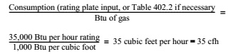
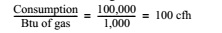
The quantity of gas to be provided at each outlet should be determined, whenever possible, directly from the manufacturer’s gas input Btu/h rating of the appliance that will be installed. In case the ratings of the appliances to be installed are not known, Table 402.2 shows the approximate consumption (in Btu per hour) of certain types of typical household appliances.To obtain the cubic feet per hour of gas required, divide the total Btu/h input of all appliances by the average Btu heating value per cubic feet of the gas. The average Btu per cubic feet of the gas in the area of the installation can be obtained from the serving gas supplier.
A.2.2 Low pressure natural gas tables.
Capacities for gas at low pressure [less than 2.0 psig (13.8 kPa gauge)] in cubic feet per hour of 0.60 specific gravity gas for different sizes and lengths are shown in Tables 402.4(1) and 402.4(2) for iron pipe or equivalent rigid pipe; in Tables 402.4(8) through 402.4(11) for smooth wall semirigid tubing; and in Tables 402.4(15) through 402.4(17) for corrugated stainless steel tubing. Tables 402.4(1) and 402.4(6) are based upon a pressure drop of 0.3-inch w.c. (75 Pa), whereas Tables 402.4(2), 402.4(9) and 402.4(15) are based upon a pressure drop of 0.5-inch w.c. (125 Pa). Tables 402.4(3), 402.4(4), 402.4(10), 402.4(11), 402.4(16) and 402.4(17) are special low-pressure applications based upon pressure drops greater than 0.5-inch w.c. (125 Pa). In using these tables, an allowance (in equivalent length of pipe) should be considered for any piping run with four or more fittings (see Table A.2.2).TABLE A.2.2
EQUIVALENT LENGTHS OF PIPE FITTINGS AND VALVESSCREWED FITTINGS1 90° WELDING ELBOWS AND SMOOTH BENDS2 45°/Ell 90°/Ell 180°close return bends Tee R/d = 1 R/d = 11/3 R/d = 2 R/d = 4 R/d = 6 R/d = 8 k factor = 0.42 0.90 2.00 1.80 0.48 0.36 0.27 0.21 0.27 0.36 L/d’ ratio4 n = 1 4 30 67 60 16 12 9 7 9 12 Nominal
pipe size,
inchesInside
diameter d,
inches,
Schedule 406L = Equivalent Length In Feet of Schedule 40 (Standard-weight) Straight Pipe6 1/2 0.622 0.73 1.55 3.47 3.10 0.83 0.62 0.47 0.36 0.47 0.62 3/4 0.824 0.96 2.06 4.60 4.12 1.10 0.82 0.62 0.48 0.62 0.82 1 1.049 1.22 2.62 5.82 5.24 1.40 1.05 0.79 0.61 0.79 1.05 11/4 1.380 1.61 3.45 7.66 6.90 1.84 1.38 1.03 0.81 1.03 1.38 11/2 1.610 1.88 4.02 8.95 8.04 2.14 1.61 1.21 0.94 1.21 1.61 2 2.067 2.41 5.17 11.5 10.3 2.76 2.07 1.55 1.21 1.55 2.07 21/2 2.469 2.88 6.16 13.7 12.3 3.29 2.47 1.85 1.44 1.85 2.47 3 3.068 3.58 7.67 17.1 15.3 4.09 3.07 2.30 1.79 2.30 3.07 4 4.026 4.70 10.1 22.4 20.2 5.37 4.03 3.02 2.35 3.02 4.03 5 5.047 5.88 12.6 28.0 25.2 6.72 5.05 3.78 2.94 3.78 5.05 6 6.065 7.07 15.2 33.8 30.4 8.09 6.07 4.55 3.54 4.55 6.07 8 7.981 9.31 20.0 44.6 40.0 10.6 7.98 5.98 4.65 5.98 7.98 10 10.02 11.7 25.0 55.7 50.0 13.3 10.0 7.51 5.85 7.51 10.0 12 11.94 13.9 29.8 66.3 59.6 15.9 11.9 8.95 6.96 8.95 11.9 14 13.13 15.3 32.8 73.0 65.6 17.5 13.1 9.85 7.65 9.85 13.1 16 15.00 17.5 37.5 83.5 75.0 20.0 15.0 11.2 8.75 11.2 15.0 18 16.88 19.7 42.1 93.8 84.2 22.5 16.9 12.7 9.85 12.7 16.9 20 18.81 22.0 47.0 105.0 94.0 25.1 18.8 14.1 11.0 14.1 18.8 24 22.63 26.4 56.6 126.0 113.0 30.2 22.6 17.0 13.2 17.0 22.6 (continued)
TABLE A.2.2—continued
EQUIVALENT LENGTHS OF PIPE FITTINGS AND VALVESMITER ELBOWS3 (No. of miters) WELDING TEES VALVES (screwed, flanged, or welded) 1-45° 1-60° 1-90° 2-90°5 3-90°5 Forged Miter3 Gate Globe Angle Swing Check k factor = 0.45 0.90 1.80 0.60 0.45 1.35 1.80 0.21 10 5.0 2.5 L/d’ ratio4 n = 15 30 60 20 15 45 60 7 333 167 83 Nominal
pipe size,
inchesInside
diameter d,
inches,
Schedule 406L = Equivalent Length In Feet of Schedule 40 (Standard-weight) Straight Pipe6 1/2 0.622 0.78 1.55 3.10 1.04 0.78 2.33 3.10 0.36 17.3 8.65 4.32 3/4 0.824 1.03 2.06 4.12 1.37 1.03 3.09 4.12 0.48 22.9 11.4 5.72 1 1.049 1.31 2.62 5.24 1.75 1.31 3.93 5.24 0.61 29.1 14.6 7.27 11/4 1.380 1.72 3.45 6.90 2.30 1.72 5.17 6.90 0.81 38.3 19.1 9.58 11/2 1.610 2.01 4.02 8.04 2.68 2.01 6.04 8.04 0.94 44.7 22.4 11.2 2 2.067 2.58 5.17 10.3 3.45 2.58 7.75 10.3 1.21 57.4 28.7 14.4 21/2 2.469 3.08 6.16 12.3 4.11 3.08 9.25 12.3 1.44 68.5 34.3 17.1 3 3.068 3.84 7.67 15.3 5.11 3.84 11.5 15.3 1.79 85.2 42.6 21.3 4 4.026 5.04 10.1 20.2 6.71 5.04 15.1 20.2 2.35 112.0 56.0 28.0 5 5.047 6.30 12.6 25.2 8.40 6.30 18.9 25.2 2.94 140.0 70.0 35.0 6 6.065 7.58 15.2 30.4 10.1 7.58 22.8 30.4 3.54 168.0 84.1 42.1 8 7.981 9.97 20.0 40.0 13.3 9.97 29.9 40.0 4.65 22.0 111.0 55.5 10 10.02 12.5 25.0 50.0 16.7 12.5 37.6 50.0 5.85 278.0 139.0 69.5 12 11.94 14.9 29.8 59.6 19.9 14.9 44.8 59.6 6.96 332.0 166.0 83.0 14 13.13 16.4 32.8 65.6 21.9 16.4 49.2 65.6 7.65 364.0 182.0 91.0 16 15.00 18.8 37.5 75.0 25.0 18.8 56.2 75.0 8.75 417.0 208.0 104.0 18 16.88 21.1 42.1 84.2 28.1 21.1 63.2 84.2 9.85 469.0 234.0 117.0 20 18.81 23.5 47.0 94.0 31.4 23.5 70.6 94.0 11.0 522.0 261.0 131.0 24 22.63 28.3 56.6 113.0 37.8 28.3 85.0 113.0 13.2 629.0 314.0 157.0 For SI: 1 foot = 305 mm, 1 degree = 0.01745 rad. Note: Values for welded fittings are for conditions where bore is not obstructed by weld spatter or backing rings. If appreciably obstructed, use values for “Screwed Fittings.” 1. Flanged fittings have three-fourths the resistance of screwed elbows and tees. 2. Tabular figures give the extra resistance due to curvature alone to which should be added the full length of travel. 3. Small size socket-welding fittings are equivalent to miter elbows and miter tees. 4. Equivalent resistance in number of diameters of straight pipe computed for a value of (f – 0.0075) from the relation (n – k/4f). 5. For condition of minimum resistance where the centerline length of each miter is between d and 21/2d. 6. For pipe having other inside diameters, the equivalent resistance may be computed from the above n values. Source: Crocker, S. Piping Handbook, 4th ed., Table XIV, pp. 100-101. Copyright 1945 by McGraw-Hill, Inc. Used by permission of McGraw-Hill Book Company. A.2.3 Undiluted liquefied petroleum tables.
Capacities in thousands of Btu per hour of undiluted liquefied petroleum gases based on a pressure drop of 0.5-inch w.c. (125 Pa) for different sizes and lengths are shown in Table 402.4(28) for iron pipe or equivalent rigid pipe, in Table 402.4(30) for smooth wall semi-rigid tubing, in Table 402.4(32) for corrugated stainless steel tubing, and in Tables 402.4(35) and 402.4(37) for polyethylene plastic pipe and tubing. Tables 402.4(33) and 402.4(34) for corrugated stainless steel tubing and Table 402.4(36) for polyethylene plastic pipe are based on operating pressures greater than 11/2 pounds per square inch (psi) (3.5 kPa) and pressure drops greater than 0.5-inch w.c. (125 Pa). In using these tables, an allowance (in equivalent length of pipe) should be considered for any piping run with four or more fittings [see Table A.2.2].A.2.4 Natural gas specific gravity.
Gas piping systems that are to be supplied with gas of a specific gravity of 0.70 or less can be sized directly from the tables provided in this code, unless the code official specifies that a gravity factor be applied. Where the specific gravity of the gas is greater than 0.70, the gravity factor should be applied.Application of the gravity factor converts the figures given in the tables provided in this code to capacities for another gas of different specific gravity. Such application is accomplished by multiplying the capacities given in the tables by the multipliers shown in Table A.2.4. In case the exact specific gravity does not appear in the table, choose the next higher value specific gravity shown.
TABLE A.2.4
MULTIPLIERS TO BE USED WITH TABLES 402.4(1)
THROUGH 402.4(22) WHERE THE SPECIFIC GRAVITY
OF THE GAS IS OTHER THAN 0.60SPECIFIC
GRAVITYMULTIPLIER SPECIFIC
GRAVITYMULTIPLIER 0.35 1.31 1.00 0.78 0.40 1.23 1.10 0.74 0.45 1.16 1.20 0.71 0.50 1.10 1.30 0.68 0.55 1.04 1.40 0.66 0.60 1.00 1.50 0.63 0.65 0.96 1.60 0.61 0.70 0.93 1.70 0.59 0.75 0.90 1.80 0.58 0.80 0.87 1.90 0.56 0.85 0.84 2.00 0.55 0.90 0.82 2.10 0.54 A.2.5 Higher pressure natural gas tables.
Capacities for gas at pressures 2.0 psig (13.8 kPa) or greater in cubic feet per hour of 0.60 specific gravity gas for different sizes and lengths are shown in Tables 402.4(5) through 402.4(7) for iron pipe or equivalent rigid pipe; Tables 402.4(12) to 402.4(14) for semirigid tubing; Tables 402.4(18) and 402.4(19) for corrugated stainless steel tubing; and Table 402.4(22)for polyethylene plastic pipe.A.3 Use of capacity tables.
A.3.1 Longest length method.
This sizing method is conservative in its approach by applying the maximum operating conditions in the system as the norm for the system and by setting the length of pipe used to size any given part of the piping system to the maximum value.To determine the size of each section of gas piping in a system within the range of the capacity tables, proceed as follows (also see sample calculations included in this Appendix):
(1) Divide the piping system into appropriate segments consistent with the presence of tees, branch lines and main runs. For each segment, determine the gas load (assuming all appliances operate simultaneously) and its overall length. An allowance (in equivalent length of pipe) as determined from Table A.2.2 shall be considered for piping segments that include four or more fittings.
(2) Determine the gas demand of each appliance to be attached to the piping system. Where Tables 402.4(1) through 402.4(24) are to be used to select the piping size, calculate the gas demand in terms of cubic feet per hour for each piping system outlet. Where Tables 402.4(25) through 402.4(37) are to be used to select the piping size, calculate the gas demand in terms of thousands of Btu per hour for each piping system outlet.
(3) Where the piping system is for use with other than undiluted liquefied petroleum gases, determine the design system pressure, the allowable loss in pressure (pressure drop), and specific gravity of the gas to be used in the piping system.
(4) Determine the length of piping from the point of delivery to the most remote outlet in the building/piping system.
(5) In the appropriate capacity table, select the row showing the measured length or the next longer length if the table does not give the exact length. This is the only length used in determining the size of any section of gas piping. If the gravity factor is to be applied, the values in the selected row of the table are multiplied by the appropriate multiplier from Table A.2.4.
(6) Use this horizontal row to locate ALL gas demand figures for this particular system of piping.
(7) Starting at the most remote outlet, find the gas demand for that outlet in the horizontal row just selected. If the exact figure of demand is not shown, choose the next larger figure left in the row.
(8) Opposite this demand figure, in the first row at the top, the correct size of gas piping will be found.
(9) Proceed in a similar manner for each outlet and each section of gas piping. For each section of piping, determine the total gas demand supplied by that section.
When a large number of piping components (such as elbows, tees and valves) are installed in a pipe run, additional pressure loss can be accounted for by the use of equivalent lengths. Pressure loss across any piping component can be equated to the pressure drop through a length of pipe. The equivalent length of a combination of only four elbows/tees can result in a jump to the next larger length row, resulting in a significant reduction in capacity. The equivalent lengths in feet shown in Table A.2.2 have been computed on a basis that the inside diameter corresponds to that of Schedule 40 (standard-weight) steel pipe, which is close enough for most purposes involving other schedules of pipe. Where a more specific solution for equivalent length is desired, this may be made by multiplying the actual inside diameter of the pipe in inches by n/12, or the actual inside diameter in feet by n (n can be read from the table heading). The equivalent length values can be used with reasonable accuracy for copper or brass fittings and bends although the resistance per foot of copper or brass pipe is less than that of steel. For copper or brass valves, however, the equivalent length of pipe should be taken as 45 percent longer than the values in the table, which are for steel pipe.
A.3.2 Branch length method.
This sizing method reduces the amount of conservatism built into the traditional Longest Length Method. The longest length as measured from the meter to the furthest remote applianceis only used to size the initial parts of the overall piping system. The Branch Length Method is applied in the following manner:(1) Determine the gas load for each of the connected appliances.
(2) Starting from the meter, divide the piping system into a number of connected segments, and determine the length and amount of gas that each segment would carry assuming that all appliances were operated simultaneously. An allowance (in equivalent length of pipe) as determined from Table A.2.2 should be considered for piping segments that include four or more fittings.
(3) Determine the distance from the outlet of the gas meter to the appliance furthest removed from the meter.
(4) Using the longest distance (found in Step 3), size each piping segment from the meter to the most remote appliance outlet.
(5) For each of these piping segments, use the longest length and the calculated gas load for all of the connected appliances for the segment and begin the sizing process in Steps 6 through 8.
(6) Referring to the appropriate sizing table (based on operating conditions and piping material), find the longest length distance in the first column or the next larger distance if the exact distance is not listed. The use of alternative operating pressures and/or pressure drops will require the use of a different sizing table, but will not alter the sizing methodology. In many cases, the use of alternative operating pressures and/or pressure drops will require the approval of both the code official and the local gas serving utility.
(7) Trace across this row until the gas load is found or the closest larger capacity if the exact capacity is not listed.
(8) Read up the table column and select the appropriate pipe size in the top row. Repeat Steps 6, 7 and 8 for each pipe segment in the longest run.
(9) Size each remaining section of branch piping not previously sized by measuring the distance from the gas meter location to the most remote outlet in that branch, using the gas load of attached appliances and following the procedures of Steps 2 through 8.
A.3.3 Hybrid pressure method.
The sizing of a 2 psi (13.8 kPa) gas piping system is performed using the traditional Longest Length Method but with modifications. The 2 psi (13.8 kPa) system consists of two independent pressure zones, and each zone is sized separately. The Hybrid Pressure Method is applied as follows:The sizing of the 2 psi (13.8 kPa) section (from the meter to the line regulator) is as follows:
(1) Calculate the gas load (by adding up the name plate ratings) from all connected appliances. (In certain circumstances the installed gas load may be increased up to 50 percent to accommodate future addition of appliances.) Ensure that the line regulator capacity is adequate for the calculated gas load and that the required pressure drop (across the regulator) for that capacity does not exceed 3/4 psi (5.2 kPa) for a 2 psi (13.8 kPa) system. If the pressure drop across the regulator is too high (for the connected gas load), select a larger regulator.
(2) Measure the distance from the meter to the line regulator located inside the building.
(3) If there are multiple line regulators, measure the distance from the meter to the regulator furthest removed from the meter.
(4) The maximum allowable pressure drop for the 2 psi (13.8 kPa) section is 1 psi (6.9 kPa).
(5) Referring to the appropriate sizing table (based on piping material) for 2 psi (13.8 kPa) systems with a 1 psi (6.9 kPa) pressure drop, find this distance in the first column, or the closest larger distance if the exact distance is not listed.
(6) Trace across this row until the gas load is found or the closest larger capacity if the exact capacity is not listed.
(7) Read up the table column to the top row and select the appropriate pipe size.
(8) If there are multiple regulators in this portion of the piping system, each line segment must be sized for its actual gas load, but using the longest length previously determined above.
The low pressure section (all piping downstream of the line regulator) is sized as follows:
(1) Determine the gas load for each of the connected appliances.
(2) Starting from the line regulator, divide the piping system into a number of connected segments and/or independent parallel piping segments, and determine the amount of gas that each segment would carry assuming that all appliances were operated simultaneously. An allowance (in equivalent length of pipe) as determined from Table A.2.2should be considered for piping segments that include four or more fittings.
(3) For each piping segment, use the actual length or longest length (if there are sub-branchlines) and the calculated gas load for that segment and begin the sizing process as follows:
(a) Referring to the appropriate sizing table (based on operating pressure and piping material), find the longest length distance in the first column or the closest larger distance if the exact distance is not listed. The use of alternative operating pressures and/or pressure drops will require the use of a different sizing table, but will not alter the sizing methodology. In many cases, the use of alternative operating pressures and/or pressure drops may require the approval of the code official.
(b) Trace across this row until the appliance gas load is found or the closest larger capacity if the exact capacity is not listed.
(c) Read up the table column to the top row and select the appropriate pipe size.
(d) Repeat this process for each segment of the piping system.
A.3.4 Pressure drop per 100 feet method.
This sizing method is less conservative than the others, but it allows the designer to immediately see where the largest pressure drop occurs in the system. With this information, modifications can be made to bring the total drop to the critical appliance within the limitations that are presented to the designer.Follow the procedures described in the Longest Length Method for Steps (1) through (4) and (9).
For each piping segment, calculate the pressure drop based on pipe size, length as a percentage of 100 feet (30 480 mm) and gas flow. Table A.3.4 shows pressure drop per 100 feet (30 480 mm) for pipe sizes from 1/2 inch (12.7 mm) through 2 inches (51 mm). The sum of pressure drops to the critical appliance is subtracted from the supply pressure to verify that sufficient pressure will be available. If not, the layout can be examined to find the high drop section(s) and sizing selections modified.
Note: Other values can be obtained by using the following equation:
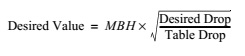
For example, if it is desired to get flow through 3/4-inch (19.1 mm) pipe at 2 inches/100 feet, multiply the capacity of 3/4-inch pipe at 1 inch/100 feet by the square root of the pressure ratio:
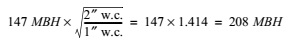
(MBH = 1000 Btu/h)
TABLE A.3.4
THOUSANDS OF BTU/H (MBH) OF NATURAL GAS PER 100 FEET OF PIPE AT VARIOUS PRESSURE DROPS AND PIPE DIAMETERSPRESSURE DROP PER
100 FEET IN INCHES
W.C.PIPE SIZES (inch) 1/2 3/4 1 11/4 11/2 2 0.2 31 64 121 248 372 716 0.3 38 79 148 304 455 877 0.5 50 104 195 400 600 1160 1.0 71 147 276 566 848 1640 For SI: 1 inch = 25.4 mm, 1 foot = 304.8 mm. A.4 Use of sizing equations.
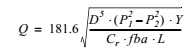
Capacities of smooth wall pipe or tubing can also be determined by using the following formulae:(1) High Pressure [1.5 psi (10.3 kPa) and above]:

(2) Low Pressure [Less than 1.5 psi (10.3 kPa)]:
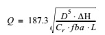
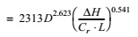
where:
Q = Rate, cubic feet per hour at 60°F and 30-inch mercury column D = Inside diameter of pipe, in. P1 = Upstream pressure, psia P2 = Downstream pressure, psia Y = Superexpansibility factor = 1/supercompressibility factor Cr = Factor for viscosity, density and temperature* = 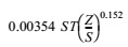
Note: See Table 402.4 for Y and Cr for natural gas and propane.
S = Specific gravity of gas at 60°F and 30-inch mercury column (0.60 for natural gas, 1.50 for propane), or = 1488µ T = Absolute temperature, °F or = t + 460 t = Temperature, °F Z = Viscosity of gas, centipoise (0.012 for natural gas, 0.008 for propane), or = 1488µ fba = Base friction factor for air at 60°F (CF = 1) L = Length of pipe, ft ΔH = Pressure drop, in. w.c. (27.7 in. H2O = 1 psi) (For SI, see Section 402.4)
A.5 Pipe and tube diameters.
Where the internal diameter is determined by the formulas in Section 402.4, Tables A.5.1 and A.5.2 can be used to select the nominal or standard pipe size based on the calculated internal diameter.TABLE A.5.1
SCHEDULE 40 STEEL PIPE STANDARD SIZESNOMINAL SIZE
(inch)INTERNAL DIAMETER
(inch)NOMINAL SIZE
(inch)INTERNAL DIAMETER
(inch)1/4 0.364 11/2 1.610 3/8 0.493 2 2.067 1/2 0.622 21/2 2.469 3/4 0.824 3 3.068 1 1.049 31/2 3.548 11/4 1.380 4 4.026 For SI: 1 inch = 25.4 mm. TABLE A.5.2
COPPER TUBE STANDARD SIZESTUBE
TYPENOMINAL OR
STANDARD SIZE (inches)INTERNAL DIAMETER
(inches)K 1/4 0.305 L 1/4 0.315 ACR (D) 3/8 0.315 ACR (A) 3/8 0.311 K 3/8 0.402 L 3/8 0.430 ACR (D) 1/2 0.430 ACR (A) 1/2 0.436 K 1/2 0.527 L 1/2 0.545 ACR (D) 5/8 0.545 ACR (A) 5/8 0.555 K 5/8 0.652 L 5/8 0.666 ACR (D) 3/4 0.666 ACR (A) 3/4 0.680 K 3/4 0.745 L 3/4 0.785 ACR 7/8 0.785 K 1 0.995 L 1 1.025 ACR 11/8 1.025 K 11/4 1.245 L 11/4 1.265 ACR 13/8 1.265 K 11/2 1.481 L 11/2 1.505 ACR 15/8 1.505 K 2 1.959 L 2 1.985 ACR 21/8 1.985 K 21/2 2.435 L 21/2 2.465 ACR 25/8 2.465 K 3 2.907 L 3 2.945 ACR 31/8 2.945 For SI: 1 inch = 25.4 mm. A.6 Use of sizing charts.
A third method of sizing gas piping is detailed below as an option that is useful when large quantities of piping are involved in a job (e.g., an apartment house) and material costs are of concern. If the user is not completely familiar with this method, the resulting pipe sizing should be checked by a knowledgeable gas engineer. The sizing charts are applied as follows:(1) With the layout developed according to Section 106.3.1 of the code, indicate in each section the design gas flow under maximum operation conditions. For many layouts, the maximum design flow will be the sum of all connected loads; however, in some cases, certain combinations of appliances will not occur simultaneously (e.g., gas heating and air conditioning). For these cases, the design flow is the greatest gas flow that can occur at any one time.
(2) Determine the inlet gas pressure for the system being designed. In most cases, the point of inlet will be the gas meter or service regulator, but in the case of a system addition, it could be the point of connection to the existing system.
(3) Determine the minimum pressure required at the inlet to the critical appliance. Usually, the critical item will be the appliance with the highest required pressure for satisfactory operation. If several items have the same required pressure, it will be the one with the greatest length of piping from the system inlet.
(4) The difference between the inlet pressure and critical item pressure is the allowable system pressure drop. Figures A.6(a) and A.6(b) show the relationship between gas flow, pipe size and pipe length for natural gas with 0.60 specific gravity.
(5) To use Figure A.6(a) (low pressure applications), calculate the piping length from the inlet to the critical appliance. Increase this length by 50 percent to allow for fittings. Divide the allowable pressure drop by the equivalent length (in hundreds of feet) to determine the allowable pressure drop per 100 feet (30 480 mm). Select the pipe size from Figure A.6(a) for the required volume of flow.
(6) To use Figure A.6(b) (high pressure applications), calculate the equivalent length as above. Calculate the index number for Figure A.6(b) by dividing the difference between the squares of the absolute values of inlet and outlet pressures by the equivalent length (in hundreds of feet). Select the pipe size from Figure A.6(b) for the gas volume required.
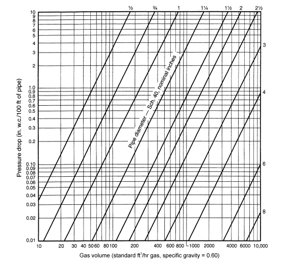
FIGURE A.6(a)
CAPACITY OF NATURAL GAS PIPING, LOW PRESSURE (0.60 WC)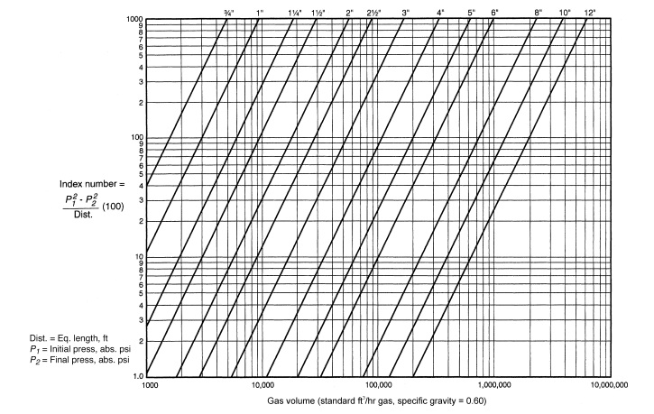
FIGURE A.6(b)
CAPACITY OF NATURAL GAS PIPING, HIGH PRESSURE (1.5 psi and above)A.7 Examples of piping system design and sizing.
A.7.1 Example 1: Longest length method.
Determine the required pipe size of each section and outlet of the piping system shown in Figure A.7.1, with a designated pressure drop of 0.5-inch w.c. (125 Pa) using the Longest Length Method. The gas to be used has 0.60 specific gravity and a heating value of 1,000 Btu/ft3 (37.5 MJ/m3).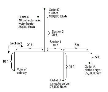
FIGURE A.7.1
PIPING PLAN SHOWING A STEEL PIPING SYSTEMSolution:
(1) Maximum gas demand for Outlet A:
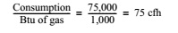
Maximum gas demain for Outlet B:
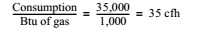
Maximum gas demain for Outlet C:
Maximum gas demain for Outlet D:
(2) The length of pipe from the point of delivery to the most remote outlet (A) is 60 feet (18 288 mm). This is the only distance used.
(3) Using the row marked 60 feet (18 288 mm) in Table 402.4(2):
(a) Outlet A, supplying 35 cfh (0.99 m3/hr), requires 1/2-inch pipe.
(b) Outlet B, supplying 75 cfh (2.12 m3/hr), requires 3/4-inch pipe.
(c) Section 1, supplying Outlets A and B, or 110 cfh (3.11 m3/hr), requires 3/4-inch pipe.
(d) Section 2, supplying Outlets C and D, or 135 cfh (3.82 m3/hr), requires 3/4-inch pipe.
(e) Section 3, supplying Outlets A, B, C and D, or 245 cfh (6.94 m3/hr), requires 1-inch pipe.
(4) If a different gravity factor is applied to this example, the values in the row marked 60 feet (18 288 mm) of Table 402.4(2) would be multiplied by the appropriate multiplier from Table A.2.4 and the resulting cubic feet per hour values would be used to size the piping.
A.7.2 Example 2: Hybrid or dual pressure systems.
Determine the required CSST size of each section of the piping system shown in Figure A.7.2, with a designated pressure drop of 1 psi (6.9 kPa) for the 2 psi (13.8 kPa) section and 3-inch w.c. (0.75 kPa) pressure drop for the 13-inch w.c. (2.49 kPa) section. The gas to be used has 0.60 specific gravity and a heating value of 1,000 Btu/ft3 (37.5 MJ/ m3).Solution:
(1) Size 2 psi (13.8 kPa) line using Table 402.4(18).
(2) Size 10-inch w.c. (2.5 kPa) lines using Table 402.4(16).
(3) Using the following, determine if sizing tables can be used.
(a) Total gas load shown in Figure A.7.2 equals 110 cfh (3.11 m3/hr).
(b) Determine pressure drop across regulator [see notes in Table 402.4(18)].
(c) If pressure drop across regulator exceeds 3/4 psig (5.2 kPa), Table 402.4(18) cannot be used. Note: If pressure drop exceeds 3/4 psi (5.2 kPa), then a larger regulator must be selected or an alternative sizing method must be used.
(d) Pressure drop across the line regulator [for 110 cfh (3.11 m3/hr)] is 4-inch w.c. (0.99 kPa) based on manufacturer’s performance data.
(e) Assume the CSST manufacturer has tubing sizes or EHDs of 13, 18, 23 and 30.
(4) Section A [2 psi (13.8 kPa) zone]
(a) Distance from meter to regulator = 100 feet (30 480 mm).
(b) Total load supplied by A = 110 cfh (3.11 m3/hr) (furnace + water heater + dryer).
(c) Table 402.4(18) shows that EHD size 18 should be used.
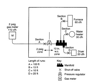
FIGURE A.7.2
PIPING PLAN SHOWING A CSST SYSTEMNote: It is not unusual to oversize the supply line by 25 to 50 percent of the as-installed load. EHD size 18 has a capacity of 189 cfh (5.35 m3/hr).
(5) Section B (low pressure zone)
(a) Distance from regulator to furnace is 15 feet (4572 mm).
(b) Load is 60 cfh (1.70 m3/hr).
(c) Table 402.4(16) shows that EHD size 13 should be used.
(6) Section C (low pressure zone)
(a) Distance from regulator to water heater is 10 feet (3048 mm).
(b) Load is 30 cfh (0.85 m3/hr).
(c) Table 402.4(16) shows that EHD size 13 should be used.
(7) Section D (low pressure zone)
(a) Distance from regulator to dryer is 25 feet (7620 mm).
(b) Load is 20 cfh (0.57 m3/hr).
(c) Table 402.4(16) shows that EHD size 13 should be used.
A.7.3 Example 3: Branch length method.
Determine the required semirigid copper tubing size of each section of the piping system shown in Figure A.7.3, with a designated pressure drop of 1-inch w.c. (250 Pa) (using the Branch Length Method). The gas to be used has 0.60 specific gravity and a heating value of 1,000 Btu/ft3 (37.5 MJ/m3).Solution:
(1) Section A
(a) The length of tubing from the point of delivery to the most remote appliance is 50 feet (15 240 mm), A + C.
(b) Use this longest length to size Sections A and C.
(c) Using the row marked 50 feet (15 240 mm) in Table 402.4(10), Section A, supplying 220 cfh (6.2 m3/hr) for four appliances requires 1-inch tubing.
(2) Section B
(a) The length of tubing from the point of delivery to the range/oven at the end of Section B is 30 feet (9144 mm), A + B.
(b) Use this branch length to size Section B only.
(c) Using the row marked 30 feet (9144 mm) in Table 402.4(10), Section B, supplying 75 cfh (2.12 m3/hr) for the range/oven requires 1/2-inch tubing.
(3) Section C
(a) The length of tubing from the point of delivery to the dryer at the end of Section C is 50 feet (15 240 mm), A + C.
(b) Use this branch length (which is also the longest length) to size Section C.
(c) Using the row marked 50 feet (15 240 mm) in Table 402.4(10), Section C, supplying 30 cfh (0.85 m3/hr) for the dryer requires 3/8-inch tubing.
(4) Section D
(a) The length of tubing from the point of delivery to the water heater at the end of Section D is 30 feet (9144 mm), A + D.
(b) Use this branch length to size Section D only.
(c) Using the row marked 30 feet (9144 mm) in Table 402.4(10), Section D, supplying 35 cfh (0.99 m3/hr) for the water heater requires 3/8-inch tubing.
(5) Section E
(a) The length of tubing from the point of delivery to the furnace at the end of Section E is 30 feet (9144 mm), A + E.
(b) Use this branch length to size Section E only.
(c) Using the row marked 30 feet (9144 mm) in Table 402.4(10), Section E, supplying 80 cfh (2.26 m3/hr) for the furnace requires 1/2-inch tubing.
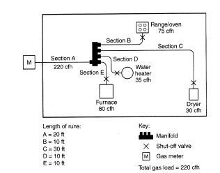
FIGURE A.7.3
PIPING PLAN SHOWING A COPPER TUBING SYSTEMA.7.4 Example 4: Modification to existing piping system.
Determine the required CSST size for Section G (retrofit application) of the piping system shown in Figure A.7.4, with a designated pressure drop of 0.5-inch w.c. (125 Pa) using the branch length method. The gas to be used has 0.60 specific gravity and a heating value of 1,000 Btu/ft3 (37.5 MJ/m3).Solution:
(1) The length of pipe and CSST from the point of delivery to the retrofit appliance (barbecue) at the end of Section G is 40 feet (12 192 mm), A + B + G.
(2) Use this branch length to size Section G.
(3) Assume the CSST manufacturer has tubing sizes or EHDs of 13, 18, 23 and 30.
(4) Using the row marked 40 feet (12 192 mm) in Table 402.4(15), Section G, supplying 40 cfh (1.13 m3/hr) for the barbecue requires EHD 18 CSST.
(5) The sizing of Sections A, B, F and E must be checked to ensure adequate gas carrying capacity since an appliance has been added to the piping system (see A.7.1 for details).
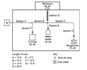
FIGURE A.7.4
PIPING PLAN SHOWING A MODIFICATION
TO EXISTING PIPING SYSTEMA.7.5 Example 5: Calculating pressure drops due to temperature changes.
A test piping system is installed on a warm autumn afternoon when the temperature is 70°F (21°C). In accordance with local custom, the new piping system is subjected to an air pressure test at 20 psig (138 kPa). Overnight, the temperature drops and when the inspector shows up first thing in the morning the temperature is 40°F (4°C).If the volume of the piping system is unchanged, then the formula based on Boyle’s and Charles’ law for determining the new pressure at a reduced temperature is as follows:

where:
T1 = Initial temperature, absolute (T1 + 459) T2 = Final temperature, absolute (T2 + 459) P1 = Initial pressure, psia (P1 + 14.7) P2 = Final pressure, psia (P2 + 14.7) 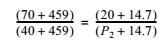
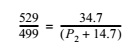
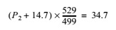
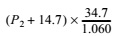
P2 = 32.7 – 14.7 P2 = 18 psig Therefore, the gauge could be expected to register 18 psig (124 kPa) when the ambient temperature is 40°F (4°C).
A.7.6 Example 6: Pressure drop per 100 feet of pipe method.
Using the layout shown in Figure A.7.1 and ΔH = pressure drop, in w.c. (27.7 in. H2O = 1 psi), proceed as follows:(1) Length to A = 20 feet, with 35,000 Btu/hr.
For 1/2-inch pipe, ΔH = 20 feet/100 feet × 0.3 inch w.c. = 0.06 in w.c.
(2) Length to B = 15 feet, with 75,000 Btu/hr.
For 3/4-inch pipe, ΔH = 15 feet/100 feet × 0.3 inch w.c. = 0.045 in w.c.
(3) Section 1 = 10 feet, with 110,000 Btu/hr. Here there is a choice:
For 1 inch pipe: ΔH = 10 feet/100 feet × 0.2 inch w.c. = 0.02 in w.c.
For 3/4-inch pipe: ΔH = 10 feet/100 feet × [0.5 inch w.c. + (110,000 Btu/hr-104,000 Btu/hr)/(147,000 Btu/hr-104,000 Btu/hr) × (1.0 inches w.c. – 0.5 inch w.c.)] = 0.1 × 0.57 inch w.c. ≈ 0.06 inch w.c.
Note that the pressure drop between 104,000 Btu/hr and 147,000 Btu/hr has been interpolated as 110,000 Btu/hr.
(4) Section 2 = 20 feet, with 135,000 Btu/hr. Here there is a choice:
For 1-inch pipe: ΔH = 20 feet/100 feet × [0.2 inch w.c. + (14,000 Btu/hr)/(27,000 Btu/hr) × 0.1 inch w.c.] = 0.05 inch w.c.
For 3/4-inch pipe: ΔH = 20 feet/100 feet × 1.0 inch w.c. = 0.2 inch w.c.
Note that the pressure drop between 121,000 Btu/hr and 148,000 Btu/hr has been interpolated as 135,000 Btu/hr, but interpolation for the 3/4-inch pipe (trivial for 104,000 Btu/hr to 147,000 Btu/hr) was not used.
(5) Section 3 = 30 feet, with 245,000 Btu/hr. Here there is a choice:
For 1-inch pipe: ΔH = 30 feet/100 feet × 1.0 inches w.c. = 0.3 inch w.c.
For 11/4-inch pipe: ΔH = 30 feet/100 feet × 0.2 inch w.c. = 0.06 inch w.c.
Note that interpolation for these options is ignored since the table values are close to the 245,000 Btu/hr carried by that section.
(6) The total pressure drop is the sum of the section approaching A, Sections 1 and 3, or either of the following, depending on whether an absolute minimum is needed or the larger drop can be accommodated.
Minimum pressure drop to farthest appliance:
ΔH = 0.06 inch w.c. + 0.02 inch w.c. + 0.06 inch w.c. = 0.14 inch w.c.
Larger pressure drop to the farthest appliance:
ΔH = 0.06 inch w.c. + 0.06 inch w.c. + 0.3 inch w.c. = 0.42 inch w.c.
Notice that Section 2 and the run to B do not enter into this calculation, provided that the appliances have similar input pressure requirements.
For SI units: 1 Btu/hr = 0.293 W, 1 cubic foot = 0.028 m3, 1 foot = 0.305 m, 1 inch w.c. = 249 Pa.